The Dance of Hardware and Imagination
Imagine a world where a flick of a wrist in software sends a robotic arm gracefully pouring coffee, or a custom-built animatronic owl turns its head to greet you. This isn’t magic—it’s the marriage of Arduino servo motors and CAD design. For makers, engineers, and hobbyists, this combination is a playground where code breathes life into static parts. Let’s dive into how these tools work together and why they’re revolutionizing DIY tech.

Arduino and Servo Motors: The Basics
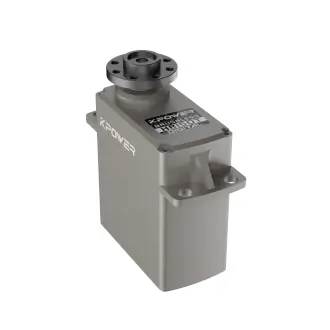
Arduino, the open-source microcontroller platform, is the brain behind countless DIY projects. Its simplicity and versatility make it ideal for controlling servo motors—compact devices that rotate with precision. Unlike standard motors, servos can hold specific angles, making them perfect for tasks requiring controlled movement, like steering a robot or adjusting a camera mount.
A typical servo has three wires: power, ground, and signal. Using Arduino’s Servo.h library, you can command these motors with just a few lines of code. For example: ```cpp
include
Servo myServo; void setup() { myServo.attach(9); // Pin 9 } void loop() { myServo.write(90); // Rotate to 90 degrees delay(1000); } ``` This code snippet moves a servo to a neutral position, but the real fun begins when you integrate sensors, buttons, or even AI to create interactive systems.
Why CAD Design Matters
While Arduino handles the logic, CAD (Computer-Aided Design) software shapes the physical form. Whether you’re 3D-printing a custom gear or laser-cutting a chassis, CAD files define how parts fit together. For servo-driven projects, CAD lets you prototype mounts, linkages, and enclosures with millimeter precision. Tools like Fusion 360, TinkerCAD, or FreeCAD offer user-friendly interfaces to draft components tailored to your servo’s dimensions.
For instance, designing a pan-tilt mechanism for a camera? Your CAD file needs precise holes to align with the servo’s mounting points and shaft. A mismatch of even 1mm could mean hours of frustrating adjustments.
Bridging the Gap: From Digital to Physical
The workflow often looks like this:
Sketch Your Idea: Start with rough sketches of your mechanism. CAD Modeling: Draft parts in software, ensuring compatibility with servo specs (e.g., SG90 vs. MG996R torque). Export and Print: Save your design as an STL or DXF file for 3D printing or CNC machining. Assemble and Test: Fit the servo into the printed part, connect it to Arduino, and debug.
Take the example of a robotic arm. The CAD file must account for servo rotation limits, weight distribution, and structural integrity. A poorly designed joint could strain the motor or snap under load.
Real-World Applications
Home Automation: Motorized blinds that adjust based on sunlight, controlled by light sensors. Robotics: A hexapod robot with 18 servos, each leg moving in sync via Arduino. Art Installations: Kinetic sculptures that respond to audience movement.
In Part 2, we’ll explore advanced CAD techniques, troubleshoot common pitfalls, and showcase jaw-dropping projects that push these tools to their limits.
Precision Meets Creativity: Advanced CAD Strategies for Servo Projects
In Part 1, we covered the basics of Arduino servos and CAD workflows. Now, let’s level up. Designing for servos isn’t just about fitting parts together—it’s about anticipating movement, stress, and real-world chaos.
Designing for Motion: Torque, Weight, and Geometry
Servo motors have limits. A common mistake is overloading a servo with a part that’s too heavy or a linkage that creates excessive torque. Use CAD software to simulate forces:
Torque Calculation: If your servo has a torque rating of 4kg/cm, ensure that the load on the arm doesn’t exceed this. Weight Distribution: Place heavier components closer to the servo’s axis to reduce strain. Clearance Checks: Animated parts need space to move without colliding. Use Fusion 360’s “Contact Solver” to test rotations.
For example, a robotic gripper CAD design must balance finger length (which amplifies torque) with the servo’s strength. Shorten the fingers or upgrade to a high-torque servo if slippage occurs.
Case Study: Building a Robotic Arm
Let’s dissect a 4-DOF (Degree of Freedom) robotic arm:
Base Rotation: A high-torque servo rotates the entire arm. Shoulder and Elbow: These servos lift and extend the arm. CAD files here need reinforced joints. Wrist and Gripper: Precision servos for delicate tasks.
In CAD, each joint is modeled with tolerances for screws and bearings. Export each part as an STL, print in PETG (durable yet lightweight), and assemble. The Arduino code uses inverse kinematics to calculate angles for smooth movement.
Troubleshooting Common Issues
Jittery Movement: Caused by power supply noise. Add a capacitor across the servo’s power leads. Overheating Motors: Redesign the CAD file to reduce load or upgrade servos. Misaligned Parts: Use parametric modeling in CAD to adjust hole sizes globally.
Pushing Boundaries: Unconventional Projects
Interactive Wearables: A servo-driven exoskeleton that assists hand movement, paired with flex sensors. Bio-Inspired Robots: A fish tail propelled by servos, with CAD-molded silicone fins. Smart Agriculture: Automatic plant-watering systems with servo-controlled valves.
The Future: AI and Generative Design
Emerging tools like generative design in Fusion 360 can auto-create optimized shapes based on load constraints. Imagine inputting your servo’s specs and letting AI draft a lightweight, ultra-strong bracket. Pair this with Arduino’s machine learning libraries, and you’ve got systems that adapt in real-time—like a solar tracker that learns cloud patterns.
Final Thoughts
Arduino servo motors and CAD design are more than tools—they’re a language for turning imagination into motion. Whether you’re a student prototyping a first robot or an artist crafting kinetic masterpieces, this synergy invites experimentation. So fire up your CAD software, wire up a servo, and let your ideas spin, pivot, and soar.


