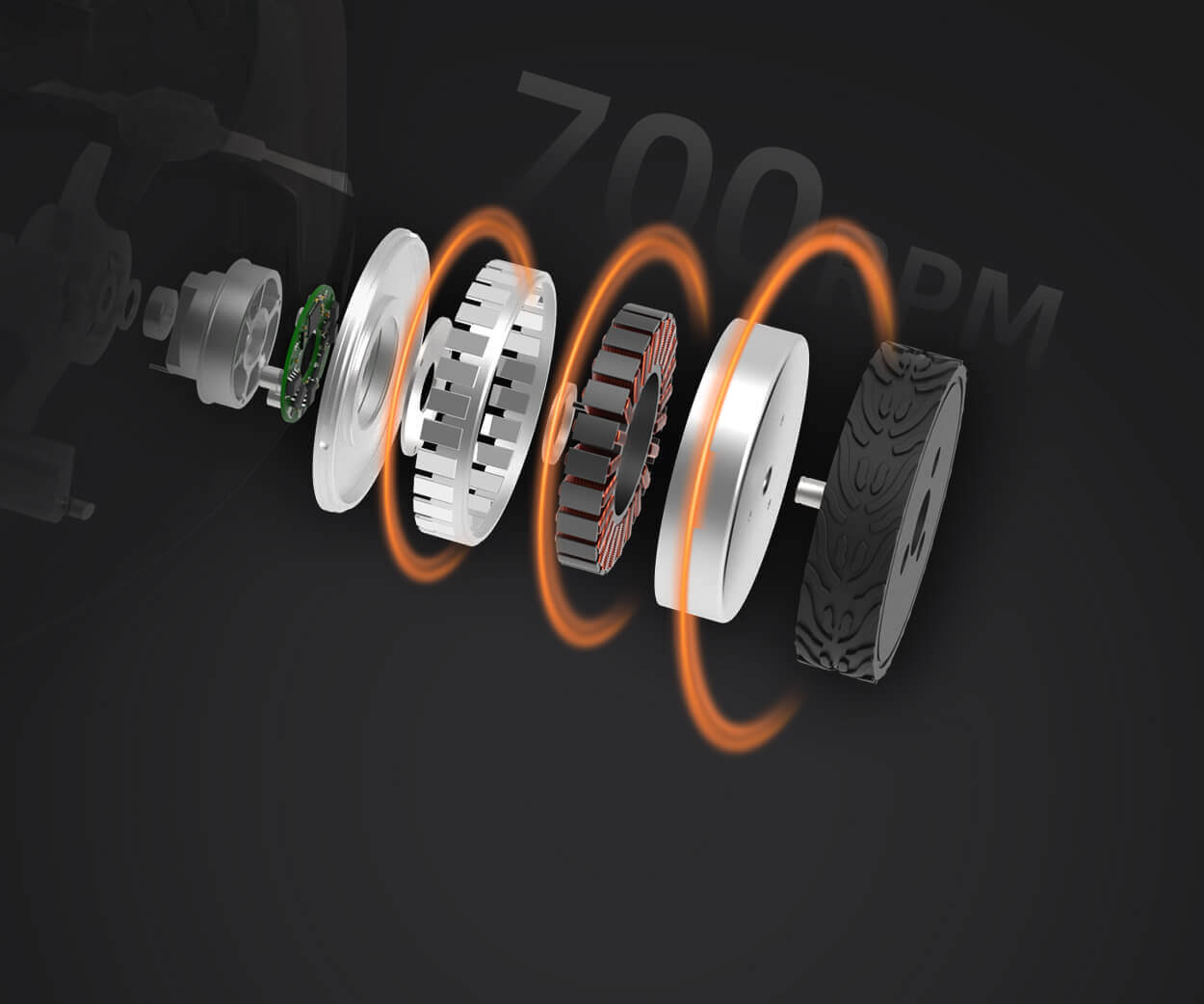
When it comes to servo motors, understanding how they function is crucial for anyone involved in automation or robotics. A key part of that understanding lies in the pin diagram of a servo motor. You may be wondering: "Why should I care about these tiny pins?" Let’s break it down.

At the heart of every servo motor is its electrical connection, and this is where the pin diagram plays a vital role. These pins connect the motor to its controller, enabling communication and power flow. Without the right pin setup, the motor simply wouldn’t work as intended. But here’s the thing — the pin diagram is not just a set of random pins; it’s carefully arranged to ensure each pin serves a unique function. Understanding this layout can save you a lot of headaches in the long run.
One of the first things you’ll notice is that a typical servo motor pin diagram usually includes pins for power, ground, signal input, and sometimes a feedback loop. The power pin is often marked as VCC or +, and it’s where the positive voltage is fed into the motor. Then, there’s the ground pin, typically labeled as GND, which ensures the motor has a stable reference point for its electrical signals.
So, let’s talk about that signal input pin for a second. This pin is the nerve center for your motor’s operation. It’s the one that receives the control signals from the controller, telling the motor how far to rotate, when to stop, and where to hold. Imagine it like a walkie-talkie – the signal input pin listens for commands and then carries them out to the motor. Without it, the motor would be like a boat without a rudder.
Now, what about feedback? Feedback is the secret sauce in many servo motors. It helps the motor know exactly where it is in its rotation, allowing it to make adjustments in real-time. If the feedback pin isn’t wired correctly, your motor might end up spinning too far or not enough, and that’s where things start to get tricky.
Here’s an example: Let’s say you’re setting up a robotic arm. You plug in the servo motor according to the pin diagram, and when you send a command to the motor, it should respond accurately. But what happens if you misplace one of those pins? Maybe the feedback is wrong or the signal is cut off — all of a sudden, your robotic arm might swing wildly or fail to move at all. That’s the kind of mistake you don’t want to make, which is why understanding the pin diagram is so important.
It’s also worth mentioning that servo motor diagrams can vary a little bit depending on the manufacturer, but the core idea remains the same: every pin has a dedicated function that supports the motor’s overall performance. At KPOWER, we’ve made sure to provide clear, detailed pin diagrams for our products so that you don’t have to guess. Whether you’re a seasoned pro or just starting out, knowing exactly what each pin does helps you get the job done faster and more accurately.
In conclusion, the pin diagram of a servo motor isn’t just for electrical engineers — it’s a crucial tool for anyone who wants their motor to work correctly. It ensures your motor gets the right signals and operates smoothly. The more familiar you become with this diagram, the better equipped you’ll be to make your servo motor perform at its best.
Established in 2005, Kpower has been dedicated to a professional compact motion unit manufacturer, headquartered in Dongguan, Guangdong Province, China. Leveraging innovations in modular drive technology, Kpower integrates high-performance motors, precision reducers, and multi-protocol control systems to provide efficient and customized smart drive system solutions. Kpower has delivered professional drive system solutions to over 500 enterprise clients globally with products covering various fields such as Smart Home Systems, Automatic Electronics, Robotics, Precision Agriculture, Drones, and Industrial Automation.


