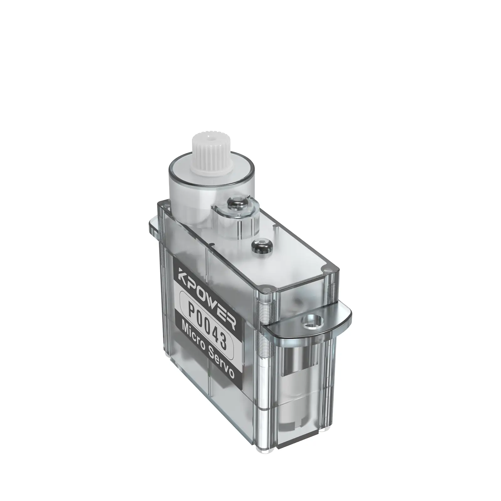
If you’ve ever held a micro servo in your hand, you’ve cradled potential. This tiny device—no larger than a matchbox—holds the power to animate robots, steer remote-controlled cars, and even bring lifelike motion to Halloween props. But to unlock its magic, you need to speak its language: the wiring diagram.

Let’s start by demystifying what a micro servo is. At its core, it’s a compact motor with a feedback control system, designed to rotate to specific angles with precision. Unlike regular motors that spin freely, servos obey commands. They’re the obedient puppets of the electronics world, waiting for your strings—or in this case, wires—to pull them into action.
But here’s the catch: wire it wrong, and your servo becomes a paperweight. Wire it right, and you’ve got a dance partner. The wiring diagram is your choreography.
The Three Wires That Rule Everything
Every micro servo has three wires: power (usually red), ground (black or brown), and signal (yellow, orange, or white). These aren’t just colors; they’re a personality test. The power wire is the extrovert—bold, demanding a steady voltage (typically 4.8–6V). The ground wire is the introvert, quietly completing the circuit. The signal wire? That’s the mediator, carrying pulse-width modulation (PWM) signals from your microcontroller (like an Arduino or Raspberry Pi) to tell the servo where to move.
Imagine this trio as a rock band. The power wire is the drummer, setting the rhythm. The ground is the bassist, anchoring the groove. The signal wire is the lead guitarist, shredding solos of precise angles. Miss a connection, and the band falls apart.
Reading Between the Lines (and Wires)
A wiring diagram for a micro servo isn’t just a schematic—it’s a story. Let’s break down a typical setup:
Power Supply: Connect the servo’s red wire to your power source’s positive terminal. Ground: Link the brown/black wire to the power supply’s negative terminal and the ground pin on your microcontroller. This shared ground is the handshake between components. Signal: Attach the yellow/orange wire to a PWM-capable pin on your microcontroller.
But here’s where things get spicy. Micro servos are divas. They hate noisy power supplies. If your servo twitches or resets, it’s probably throwing a tantrum over voltage drops. Solution? Add a capacitor across the power and ground lines, or use a separate battery for the servo.
Common Pitfalls (and How to Avoid Them)
Overloading the Power Source: Microcontrollers can’t handle high current. Power your servo separately if you’re using multiple servos or heavy loads. PWM Confusion: Not all microcontroller pins output PWM. Check your board’s specs. Pin 9 on an Arduino Uno? Good to go. Pin 13? Nope. Cable Chaos: Keep wires tidy. A tangled mess isn’t just ugly—it’s a short circuit waiting to happen.
Why This Matters Beyond the Bench
Understanding servo wiring isn’t just about making things move. It’s about dialogue. When you wire a servo, you’re not just connecting circuits—you’re teaching a machine to listen. Every pulse sent through the signal wire is a verb: rotate, hold, return. And the servo’s response—a smooth 180-degree sweep or a jittery stumble—tells you whether you’ve communicated clearly.
So next time you stare at a wiring diagram, don’t see lines and symbols. See a script. Your servo is waiting for its cue.
Now that we’ve covered the basics, let’s dive into the soul of micro servo wiring: creativity. Because once you’ve mastered the diagram, you’re not just an engineer—you’re a conductor.
Advanced Wiring: Beyond the Breadboard
The real fun begins when you integrate servos into complex systems. Take a robotic arm, for example. Each joint is a servo, each movement a symphony of signals. But wiring this requires strategy:
Daisy-Chaining Power: Use a common power rail for multiple servos, but calculate the total current draw. Six servos at 500mA each? That’s 3A—a job for a beefy power supply. Signal Isolation: Servos can introduce electrical noise. Opt for opto-isolators or dedicated servo controllers to keep signals clean. Cable Management: Sleeving wires or using ribbon cables isn’t just for aesthetics. It prevents interference and makes troubleshooting easier.
The Art of Troubleshooting
Even experts face glitches. Let’s troubleshoot a classic scenario: The servo hums but doesn’t move.
Check the signal: Use a multimeter or oscilloscope to see if PWM pulses are reaching the servo. Voltage Drop Test: Measure the voltage at the servo’s pins under load. If it sags below 4.8V, your power supply is underpowered. Swap Components: Test the servo with a known-good circuit. If it works, the issue is elsewhere.
Creative Hacks for Unconventional Projects
Micro servos aren’t just for robots. Here’s how to bend the rules:
Analog Control: Replace the microcontroller with a potentiometer. Wire the pot’s output to the servo’s signal line, and now you’ve got manual control. Serial Servos: Use a servo shield or I2C/PWM driver to control dozens of servos with just two wires. Reverse Engineering: Modify a servo for continuous rotation by disengaging the internal potentiometer. Voilà—a gearmotor!
Case Study: The Animatronic Owl
Let’s apply this to a real project. Imagine building an owl that turns its head when someone approaches. Here’s the wiring breakdown:
Motion Sensor: A PIR sensor detects movement and sends a signal to the Arduino. Microcontroller: The Arduino processes the input and triggers the servo. Servo Mechanism: The servo rotates the owl’s head via a 3D-printed linkage.
The wiring diagram becomes a narrative: sensor → brain → muscle. Each connection is a plot point.
The Philosophy of Wiring
At its heart, wiring a micro servo is an act of trust. You’re bridging the gap between human intention and machine action. Every time you plug in a wire, you’re asking, “Do we understand each other?” And when the servo whirs to life, the answer is a resounding yes.
So go ahead—grab that servo, sketch that diagram, and start a conversation. The hidden language of micro servos is waiting for you to speak it.


