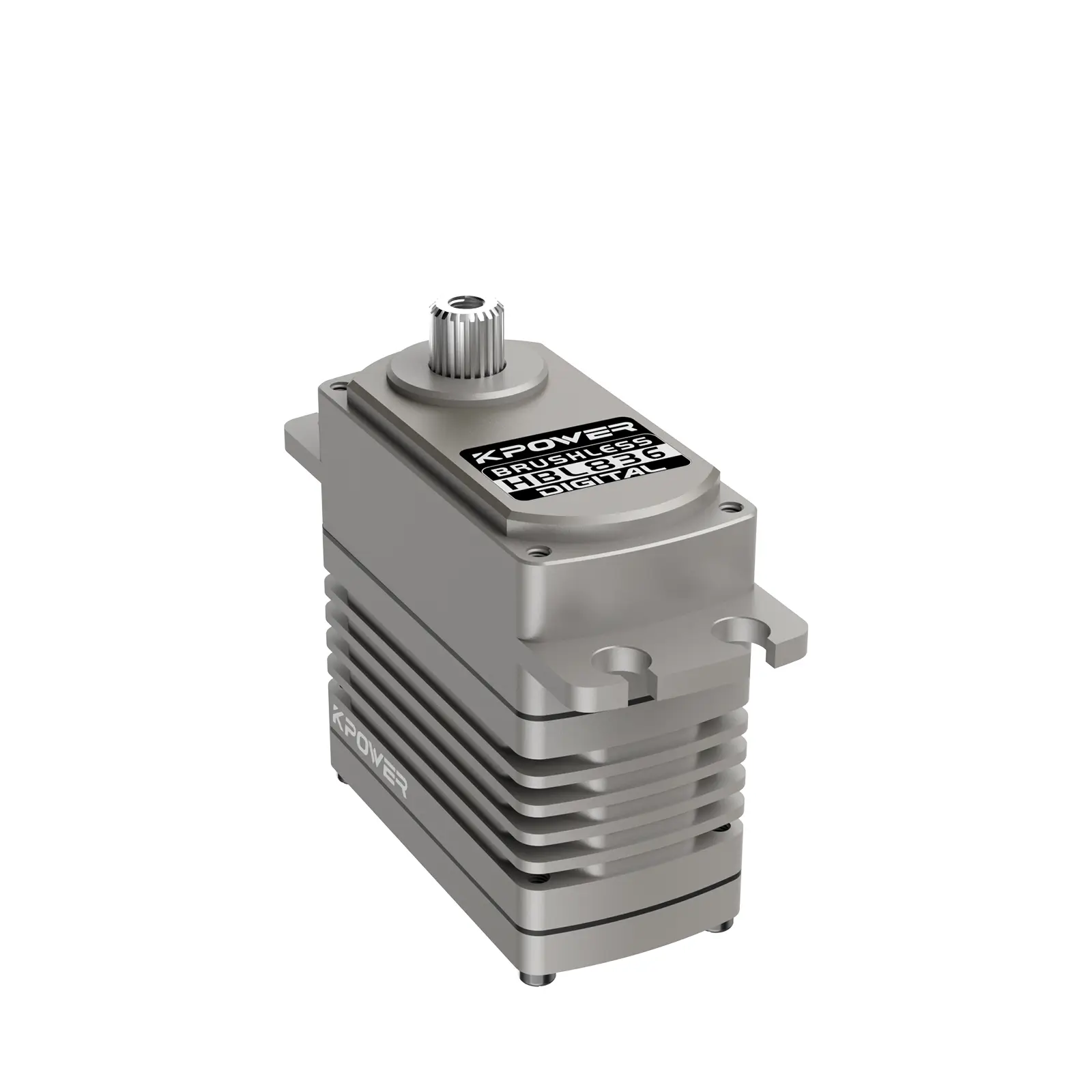
In the expansive realm of robotics, automation, and mechanical control systems, the servo motor stands out as a fundamental building block. It is the heartbeat behind precise positional movements, whether in a robotic arm, an RC car, a drone, or industrial machinery. To harness its full potential, understanding the internal wiring, especially the diagram pins, is paramount—these tiny connectors form the bridge connecting the servo's internal electronics to the outside world.

The Anatomy of a Servo Motor
Before diving into the pins, let's briefly touch on what a servo motor is. Unlike simple DC motors that just spin, a servo motor incorporates a small control circuit and a feedback mechanism called a potentiometer. This allows the motor to rotate to and maintain a specified position, making it incredibly useful for tasks requiring accuracy. Typically, a servo motor consists of:
Motor (rotor and stator) Gearbox Control circuit (usually a PWM driver) Feedback sensor (potentiometer)
The control circuit interprets input signals to position the motor accurately, translating electrical pulses into physical movement.
The Significance of the Diagram Pins
The diagram pins of a servo motor are the physical interface through which it communicates and receives power. Proper understanding of these pins enables accurate wiring, troubleshooting, and integration into larger systems. While different servo models might slightly vary, most common hobby servo motors feature a standard pin configuration that can be summarized as three main connections:
Power (Vcc) Ground (GND) Signal (PWM)
Commonly Used Pins and Their Functions
Let's analyze these pins in detail:
Vcc (Power Supply Pin): This pin supplies voltage to the servo's internal circuitry and motor. Most hobby servos operate at a voltage range of 4.8V to 6V. Providing a stable power source is critical; fluctuations can cause jitter, stalling, or complete failure.
GND (Ground Pin): The ground establishes a reference point for circuit operations. It completes the electrical circuit, ensuring that the servo's internal components can function correctly.
Signal (Control Input): The signal pin is where the control command is injected, usually in the form of a PWM (Pulse Width Modulation) signal. The width of the pulse (typically between 1ms and 2ms) dictates the position of the servo shaft, while a continuous series of pulses maintains the position.
Wiring Considerations
When connecting a servo motor, meticulous attention to wiring is vital:
Color Coding: Usually, the Vcc wire is red, GND is black or brown, and signal is yellow, white, or orange. However, always verify by checking the documentation or labels.
Power Supply Stability: Many hobbyists recommend powering servos from a dedicated power source rather than a single microcontroller pin, especially when operating multiple servos, to prevent voltage drops and resets.
Connections and Pinouts: Use proper connectors and avoid loose wiring. Ensuring correct polarity prevents damage and unintended operation.
The Role of the Diagram in Troubleshooting and Design
A detailed diagram pinout acts as a roadmap. For engineers designing complex robotics, understanding the pin configuration aids in:
Diagnosing wiring errors: Miswired pins typically lead to no response or erratic behavior. Modifying or customizing wiring setups: For example, adding additional sensors or signal conditioners. Designing PCB layouts: Precise placement of pins ensures reliable connections and reduces electromagnetic interference.
Variations in Servo Motor Pins
While the majority of hobby servos adhere to the three-pin standard, certain specialized or industrial servos might include additional contacts such as:
Sensor wires for more advanced feedback Enable pins for controlling power Dual signal lines for redundant control
In such cases, consulting the datasheet or manufacturer’s documentation becomes crucial to accurately interpret pin functions.
Stay tuned for Part 2, where we delve into advanced wiring techniques, common troubleshooting strategies, and practical tips for integrating servo motor diagram pins into various projects.
Established in 2005, Kpower has been dedicated to a professional compact motion unit manufacturer, headquartered in Dongguan, Guangdong Province, China.


