


Looking for a suitable motor?


小编
Published2025-10-15
Sure! Here's the first part of the soft article on "Servo Motor Internal Diagram."
Unraveling the Secret World Inside a Servo Motor
When it comes to automation, robotics, or even high-precision manufacturing, servo motors are the unsung heroes powering smooth, accurate, and reliable movement. These miniature marvels blend complex electromechanical components into a compact package, and understanding their internal structure can give engineers, students, and enthusiasts alike a window into the marvel of modern motion control.
At its core, a servo motor is designed to provide precise control of angular or linear position, velocity, and acceleration. Unlike simple motors that just spin freely when powered, servos incorporate intricate feedback mechanisms and advanced electronic controls that allow for high fidelity in motion. To really appreciate how they achieve this, let's delve into their internal diagram and understand each critical component.
The Basic Building Blocks of a Servo Motor
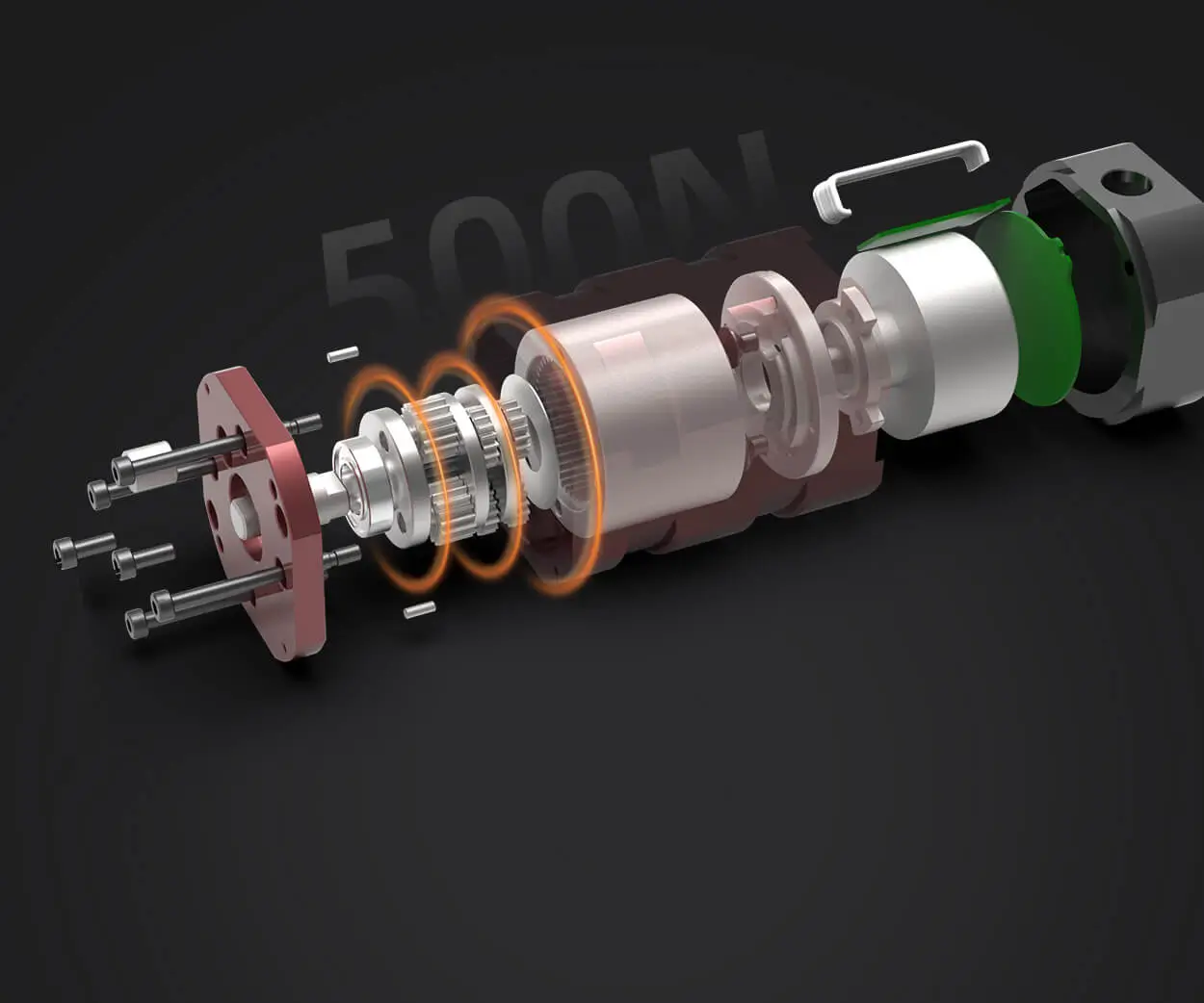
Typically, the internal diagram of a servo motor involves several interconnected parts: the motor itself, the feedback device (usually a potentiometer or encoder), the gear train, and the control circuitry including a driver or amplifier. Each part plays a vital role in ensuring the servo can fulfill its high-precision functions.
The Motor (Brushless or Brushed)
The heart of a servo motor is its motor—the primary electromechanical device that converts electrical energy into rotational motion. Depending on the application, servo motors may be brushed DC motors or brushless DC motors. Brushless motors are widely preferred in high-precision applications due to their durability and efficiency.
In a typical internal diagram, you'll see the stator windings (for brushless motors) or brushes and commutator (for brushed motors). The windings are stationary coils wrapped around magnetic poles. When energized with current, they generate magnetic fields that interact with the rotor, causing it to turn.
The rotor, often embedded with permanent magnets in brushless motors, is the rotating part that responds to the electromagnetic forces created in the stator. Its position is critical to control, which is where the feedback system comes into play.
Feedback Device (Encoder or Potentiometer)
One of the defining features of a servo motor is its ability to detect and report its position. This is achieved through feedback mechanisms. A potentiometer provides continuous analog feedback corresponding to the rotor’s position, while encoders provide digital signals.
Potentiometer: Connected directly to the rotor shaft, providing an analog voltage proportionate to the position. Encoder: Uses optical or magnetic sensors to generate pulses for high-resolution digital position data. Gear Train
Most servo motors incorporate a series of gear reductions to magnify the torque and refine positional control. Inside the internal diagram, gear trains—comprising spur gears, planetary gears, or harmonic drives—translate high-speed, low-torque outputs into low-speed, high-torque motion, suitable for precise positioning.
Control Circuitry and Driver
The control circuitry interprets the signals from the feedback device. It compares the current position with the desired command and computes an error signal. This information is then fed into a driver or amplifier that manages the power supplied to the motor, adjusting speed and torque accordingly.
In the internal diagram, you’ll find a comparison block—often called a comparator or controller—that processes the feedback and the command signals, driving the motor via pulse-width modulation (PWM) or other modulation techniques.
A stable and adequate power supply is critical. It provides the necessary current and voltage to the motor and control circuitry for smooth operation and responsive adjustments.
Understanding How It All Comes Together
Imagine the internal diagram as a microcosm of a highly synchronized dance. The controller continuously sends position commands, and the feedback device reports the current position back nearly instantaneously. The control circuitry then calculates the difference—the error—and adjusts the motor’s input accordingly. This closed-loop system ensures the servo motor maintains perfect position or velocity, even under varying loads or external disturbances.
In more sophisticated designs, the internal diagram also includes diagnostic components such as self-tuning algorithms, thermal sensors, and protective circuits. These features enhance durability, performance, and safety, especially in demanding industrial environments.
Kpower has delivered professional drive system solutions to over 500 enterprise clients globally with products covering various fields such as Smart Home Systems, Automatic Electronics, Robotics, Precision Agriculture, Drones, and Industrial Automation.
Update:2025-10-15
Contact Kpower's product specialist to recommend suitable motor or gearbox for your product.


