


Looking for a suitable motor?


小编
Published2025-10-15
Introduction to Servo Motors and Potentiometers
When it comes to building DIY projects, the combination of an Arduino board, a potentiometer, and a servo motor can bring exciting possibilities to life. Whether you're constructing a robotic arm, a camera pan system, or an automated door, learning how to control a servo motor with a potentiometer is a fundamental skill in electronics. In this guide, we’ll walk you through everything you need to know about connecting a potentiometer to an Arduino to control a servo motor, from basic wiring to writing the code.
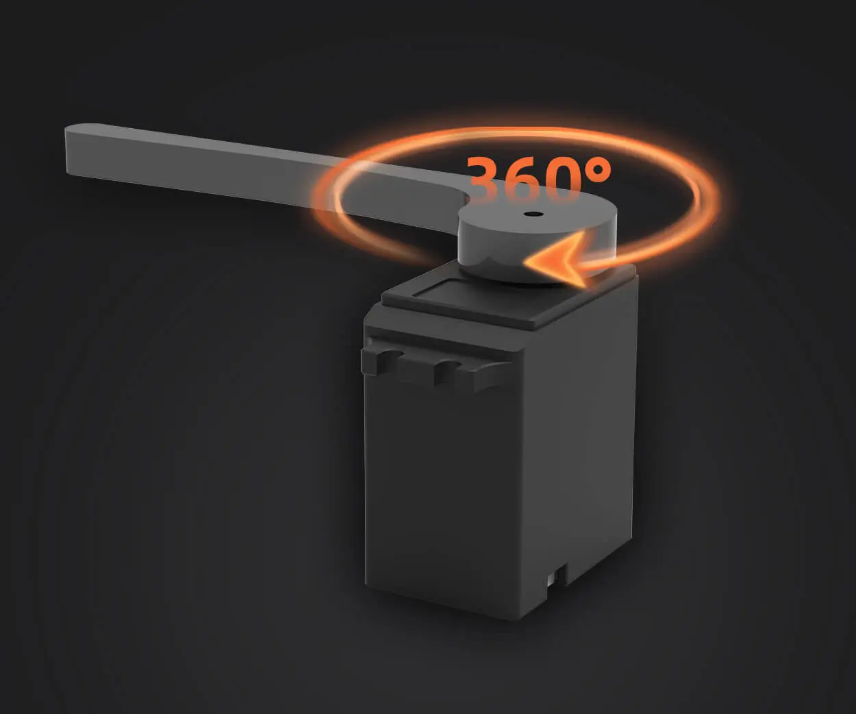
A servo motor is a versatile, precise actuator commonly used in robotics, model airplanes, and industrial machinery. Unlike regular motors, which rotate continuously, servo motors rotate to a specific angle and hold that position. They have built-in feedback mechanisms that ensure they stop at the right position, making them perfect for applications that require accuracy, like steering mechanisms or adjusting camera angles.
A typical servo motor consists of a DC motor, a set of gears, a feedback sensor (like a potentiometer), and a controller circuit. The control signal sent to the servo motor determines the position it should rotate to, and the feedback sensor ensures the motor stays at the desired angle.
Understanding Potentiometers
A potentiometer is a variable resistor, commonly used as an input device in electronics. By adjusting the potentiometer’s knob, you change the resistance, which in turn alters the voltage sent through the device. In this case, the potentiometer will act as an analog input, sending a signal to the Arduino board, which will process it and control the servo motor accordingly.
The potentiometer has three pins: one for power (typically 5V), one for ground (GND), and one for the signal output. By rotating the knob, the output voltage varies between 0V and 5V, which we can read with the Arduino's analog input pin.
What You’ll Need for This Project
Before diving into the wiring and coding, ensure you have the following components ready:
Arduino Board: Any version of Arduino (e.g., Arduino Uno, Arduino Nano) will work.
Servo Motor: A standard 9g or 18g servo motor.
Potentiometer: A 10k ohm potentiometer is commonly used for such projects.
Jumper Wires: For connecting components.
Breadboard: Optional, for easy wiring.
Power Supply: For the Arduino and the servo motor (depending on your setup).
Now that you understand the basics, it’s time to wire everything up. Follow the steps below to connect the potentiometer to your Arduino and the servo motor.
Connect the Potentiometer:
Connect one of the outer pins of the potentiometer to 5V on the Arduino.
Connect the other outer pin to GND (Ground).
Connect the middle pin (the wiper) to one of the Arduino’s analog pins (e.g., A0).
Connect the Servo Motor:
Connect the servo’s red wire to the 5V pin on the Arduino.
Connect the servo’s brown or black wire to GND.
Connect the servo’s yellow or orange wire (signal) to one of the digital pins (e.g., pin 9) on the Arduino.
Once you’ve connected all the components, double-check your wiring for correctness to avoid any damage to the components.
Now it’s time to write the Arduino code that will interpret the potentiometer’s values and control the servo’s position accordingly. Below is a simple example code to get you started:
#include // Include the Servo library
Servo myServo; // Create a servo object to control the servo motor
int potPin = A0; // Pin connected to the potentiometer
int potValue = 0; // Variable to store potentiometer reading
int angle = 0; // Variable to store the calculated angle for the servo
myServo.attach(9); // Attach the servo to pin 9
Serial.begin(9600); // Start serial communication for debugging
potValue = analogRead(potPin); // Read the potentiometer value (0-1023)
angle = map(potValue, 0, 1023, 0, 180); // Map the potentiometer value to an angle (0-180)
myServo.write(angle); // Move the servo to the corresponding angle
Serial.print("Potentiometer Value: ");
Serial.print(potValue); // Print potentiometer value for debugging
Serial.print(" | Servo Angle: ");
Serial.println(angle); // Print the calculated servo angle
delay(15); // Delay to allow the servo to reach the position
Let’s break down what the code does:
Servo Library: The code begins by including the Servo library, which allows easy control of the servo motor.
Pin Setup: The potentiometer is connected to analog pin A0, and the servo is attached to pin 9.
Reading the Potentiometer: The analogRead() function reads the value from the potentiometer, which ranges from 0 (minimum) to 1023 (maximum).
Mapping the Value: The map() function converts the potentiometer’s 0–1023 value into a 0–180 range suitable for the servo motor’s angle.
Controlling the Servo: The myServo.write() function sends the calculated angle to the servo motor, which adjusts its position.
Serial Output: The code also prints the potentiometer and servo values to the Serial Monitor for debugging purposes.
Once you’ve uploaded the code to your Arduino, rotate the potentiometer knob. You should see the servo motor’s position change in sync with the potentiometer’s adjustment. The Serial Monitor will display the potentiometer value and the corresponding servo angle.
If the servo doesn’t move, make sure the wiring is correct and the servo is properly connected to the power source. Also, check that the potentiometer is properly connected and providing a varying voltage. If necessary, adjust the delay or ensure that the servo is getting enough power.
Advanced Tips for Servo Control
Once you’ve mastered basic servo control with a potentiometer, there are several ways to enhance your project for more advanced functionality.
Instead of controlling just one servo, you can control multiple servos using the same potentiometer or multiple potentiometers. To control more than one servo, you would need to create more servo objects and attach them to different pins. You can use multiple potentiometers to control each servo independently, or you can implement a method to control multiple servos with a single potentiometer by adjusting their movement algorithm.
Here’s a simple example of controlling two servos with two potentiometers:
potValue1 = analogRead(potPin1);
potValue2 = analogRead(potPin2);
angle1 = map(potValue1, 0, 1023, 0, 180);
angle2 = map(potValue2, 0, 1023, 0, 180);
In this example, each potentiometer controls its corresponding servo, and both servos can move independently.
2. Implement Smooth Movement
Sometimes, servo motors can move abruptly, causing jerky motion. If you want smoother transitions, you can gradually move the servo motor from one position to another. To do this, you can implement a small delay between each movement, so the servo moves step by step.
Here’s an example that smooths out the movement:
int prevAngle = 0; // To store the previous angle
potValue = analogRead(potPin);
currentAngle = map(potValue, 0, 1023, 0, 180);
// Gradually move the servo to the new angle
if (abs(currentAngle - prevAngle) > 1) {
if (currentAngle > prevAngle) {
myServo.write(prevAngle);
This modification ensures that the servo moves in small steps, making the motion smoother and more controlled.
3. Implementing a Button for Additional Control
You can also add buttons to control the servo motor along with the potentiometer. For example, pressing a button could change the speed or reverse the direction of the servo.
Established in 2005, Kpower has been dedicated to a professional compact motion unit manufacturer, headquartered in Dongguan, Guangdong Province, China.
Update:2025-10-15
Contact Kpower's product specialist to recommend suitable motor or gearbox for your product.


