


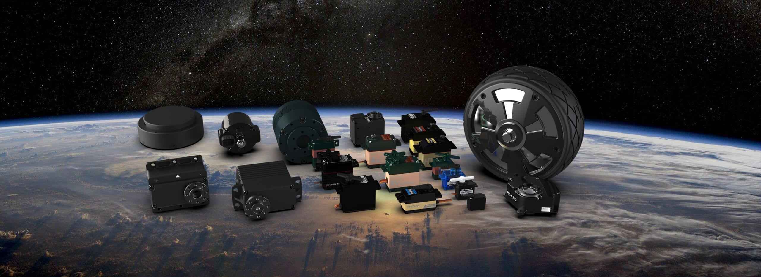
Looking for a suitable motor?


小编
Published2025-10-15
Sure! Here's the first part of the soft article on "Gear Motor Working Principle" following your specifications:
Introduction: The Synergy of Power and Precision Imagine a world where machines move seamlessly, from tiny electronic devices to massive industrial equipment. At the heart of many of these innovations lies a marvel of engineering known as the gear motor. This tiny but potent device is responsible for transforming electrical energy into controlled mechanical motion, powering a myriad of applications that keep our modern world functioning smoothly.
At its core, a gear motor is essentially an electric motor combined with a gear reducer. While the motor provides the initial motion, the gear system refines that motion, adjusting speed, torque, and direction to fit specific needs. It’s this perfect union that makes gear motors so versatile, reliable, and efficient.
Understanding the Basic Components To appreciate the working principle of a gear motor, one must first understand its primary parts:
Electric Motor: Usually a direct current (DC) or alternating current (AC) motor that converts electrical energy into rotational motion. Gearbox or Gear Reducer: A set of gears (spur, helix, worm, or planetary) that modify the motor’s output, adjusting speed and torque. Shafts and Mountings: Elements that transmit motion to external components or systems. Magnets and Windings: Critical for electromagnetic operation, creating the magnetic field necessary for motion.
Electromagnetic Foundations At the heart of most gear motors is an electromagnetic motor principle. When electrical current flows through the motor's windings, it produces a magnetic field. This magnetic field interacts with fixed magnets (or sometimes electromagnets), generating a force that causes the rotor (the rotating part) to turn. This process hinges on fundamental electromagnetic laws—Faraday’s and Lorentz’s principles—that describe how magnetic fields and electrical currents produce motion.
The Motor’s Operating Cycle In simple terms, the motor operates through a cycle of magnetic attraction and repulsion:
Current Flow: Electrical current enters the windings, creating a magnetic field. Magnetic Interaction: The magnetic field attracts or repels the rotor’s magnets, causing it to spin. Rotation and Mechanical Output: The rotor’s spinning motion is transferred via the shaft. Continuous Rotation: Commutators, brushes, and circuitry (in brushed motors) or electronic controllers (in brushless motors) ensure the magnetic forces keep the rotor turning smoothly.
This electromagnetic principle allows for precise control over speed and torque by varying the electrical input, making gear motors adaptable to countless tasks.
The Role of Gears: Amplifying Power and Precision While the motor provides the rotational energy, the gears are responsible for customizing that energy into usable mechanical output. Gears accomplish this by modifying the speed-torque relationship—the fundamental gear ratio. Size and arrangement determine whether the output is faster with less torque or slower with more torque.
For example, a high gear ratio reduces speed but amplifies torque, ideal for heavy lifting or driving mechanisms requiring strong force. Conversely, a low gear ratio maintains higher speeds but offers less torque, suitable for tasks like conveyor belts or fans.
Types of Gears Used in Gear Motors Different gear arrangements serve specific purposes:
Spur Gears: Simple, straight-toothed gears offering high efficiency for moderate power transmission. Helical Gears: Angled teeth that allow smoother, quieter operation, suited for higher speeds. Worm Gears: A screw and gear combination providing high reduction ratios and self-locking features. Planetary Gears: Multiple gears working together, providing compactness, high torque, and versatility.
Understanding Gear Ratios Gear ratios dictate how many turns the motor shaft makes relative to the output shaft:
Gear Reduction: Motor turns multiple times for fewer output revolutions, increasing torque. Gear Multiplication: For increasing speed at the expense of torque (less common in standard gear motors).
Manufacturers specify gear ratios to match the intended application, ensuring the motor’s output aligns with operational demands.
Operational Principles in Action In practical terms, when an electric gear motor receives power:
The motor’s electromagnetic system generates continuous rotary motion. This motion is transferred to the gearset, where it’s transformed to change the speed or torque. The result is a controlled, reliable mechanical drive capable of performing tasks from opening a robotic arm to moving heavy machinery.
In the next part, we'll delve into the different types of gear motors, their design considerations, and real-world examples demonstrating their remarkable versatility.
Leveraging innovations in modular drive technology, Kpower integrates high-performance motors, precision reducers, and multi-protocol control systems to provide efficient and customized smart drive system solutions.
Update:2025-10-15
Contact Kpower's product specialist to recommend suitable motor or gearbox for your product.


