


Looking for a suitable motor?


小编
Published2025-10-15
Understanding the Heart of Automation—Servo Motors and Their Significance
In the universe of robotics and automation, few components are as pivotal as the servo motor. Whether it's the precise movement of robotic arms, drone stabilization, camera gimbals, or even advanced manufacturing robots, the humble servo motor quietly powers these innovations with remarkable accuracy and control. But what exactly makes these motors so special? To truly appreciate their power, we need to delve into the core idea behind their working—beginning with their structure, operation principles, and the role played by their diagrams.
At its simplest, a servo motor is a rotary or linear actuator that allows for precise control of angular or linear position, velocity, and acceleration. Unlike traditional motors that run continuously, servo motors are equipped with feedback mechanisms—mostly encoders or resolvers—which send data back to a control system, ensuring the motor's output matches the desired input.
This feedback loop is what allows servo motors to perform highly controlled movements, making them ideal for applications requiring precision. They come in various types, with the most common being DC servo motors, AC servo motors, and brushless DC motors, each tailored to different operational needs.
Decoding the Working Diagram
A typical "servo motor working diagram" visually represents the flow of power, control signals, feedback, and mechanical components inside the motor system. It's like a map that guides us through the motor’s inner workings.
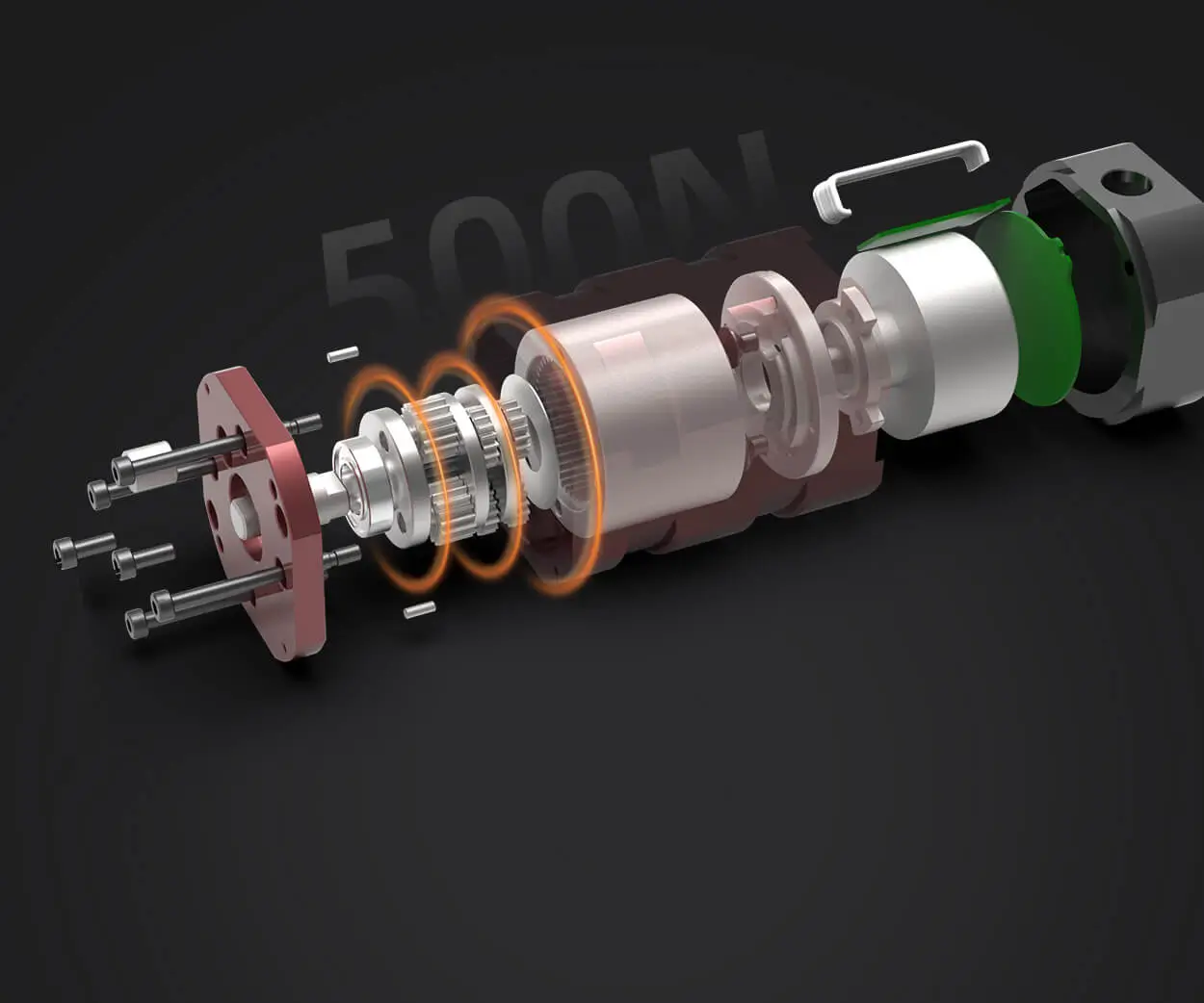
Imagine the diagram as layered; at the core, you have the motor's rotor and stator—similar to the engine of a machine. Outside this core are sensors, control circuits, and power supplies. Connecting these components are pathways carrying electrical signals, all working in concert to produce precise movements.
Core Components in the Diagram:
The Motor (Rotor and Stator): The heart of the device, where electromagnetic forces generate motion. The rotor is the part that turns, while the stator remains stationary, creating magnetic fields.
Feedback Devices (Encoders or Resolvers): These sensors measure the position or speed of the rotor. In the diagram, they are depicted as small devices attached to or integrated with the rotor.
Control Circuit: Usually represented as a microcontroller or a dedicated servo driver. This component interprets the input commands and compares them with feedback data to determine the correction needed.
Power Supply: Delivering the necessary energy to operate both the motor and control electronics, often shown as voltage sources in the diagram.
Amplifier or Driver Circuit: Converts the control signals into high-current pulses that drive the motor. Think of it as the motor’s power booster.
How These Components Interact
In the working diagram, the process begins with a command signal, often from a microcontroller or PLC (Programmable Logic Controller). This command indicates the desired position, speed, or torque.
The control circuit processes this input and sends a control signal to the driver. The driver supplies current to the motor based on this signal. As the motor runs, the encoder or resolver continuously monitors its position and speed, feeding this data back to the control circuit.
The control system compares the feedback with the command, determining whether the motor needs to increase, decrease, or stop. If, for example, the motor has not reached the target position, the control circuit adjusts the voltage and current accordingly, creating a dynamic loop known as a feedback control loop.
This real-time adjustment is what grants the servo motor its incredible finesse. The system operates so swiftly that the motor's position can be corrected thousands of times per second, ensuring movements are smooth and accurate.
Diving Deeper: Closed-Loop vs. Open-Loop Systems
The working diagram primarily depicts a closed-loop system—where feedback continuously informs control adjustments. This is what distinguishes servo systems from simple DC motors, which operate in an open-loop configuration, running at a set speed regardless of load or position.
In a closed-loop system, the feedback ensures stability and precision, making servo motors excellent choices for applications where accuracy cannot be compromised, like robotic surgery or CNC machinery.
Visualizing the Diagram in Action
Picture a robotic arm performing a pick-and-place task. Its joint movements are controlled by servo motors governed by such a working diagram. As the joint reaches a position, the encoder signals this position back to the control circuit. If there's a discrepancy, say, the joint is slightly off, the control system swiftly adjusts the motor's input, correcting the position with finesse—a process so rapid that the entire motion appears seamless and natural.
Key Factors Affecting Servo Motor Performance
While the diagram provides a blueprint of the internal processes, practical factors influence how well these systems perform:
Accuracy of Feedback Devices: Higher resolution encoders translate to finer control.
Control Algorithm Efficiency: Proportional, Integral, Derivative (PID) controllers are standard, but more sophisticated algorithms can improve stability and responsiveness.
Power and Heat Management: Proper heat dissipation and power supply ratings ensure longevity and consistent performance.
Mechanical Load: The weight and inertia of the attached equipment impact torque requirements and response time.
Interested in the next layer of understanding? In Part 2, we'll explore real-world applications of these diagrams, how to interpret different types of servo motor working diagrams, troubleshooting tips, and future trends shaping the evolution of servo motor technology.
Leveraging innovations in modular drive technology, Kpower integrates high-performance motors, precision reducers, and multi-protocol control systems to provide efficient and customized smart drive system solutions.
Update:2025-10-15
Contact Kpower's product specialist to recommend suitable motor or gearbox for your product.


