


Looking for a suitable motor?


小编
Published2025-10-15
Introduction to Brushless Servo Motors
In the world of automation, robotics, and high-precision machinery, brushless servo motors have become the gold standard for accurate motion control. These sleek, efficient motors combine the advantages of brushless DC motors with sophisticated control systems, enabling seamless performance in applications ranging from CNC machines to drone flight stabilization.
The core idea behind a brushless servo motor lies in its design. Unlike brushed motors, which have brushes that commutate the current, brushless motors—often termed BLDCs—rely on electronic commutation to switch current through their coils. This results in less wear and tear, higher reliability, and often, better energy efficiency.
However, the true power of brushless servo motors doesn't just rest on their hardware; it truly shines through their control systems. Mastering how to control these motors involves understanding their electrical architecture, feedback mechanisms, and control algorithms. Whether you're an engineer designing a robotic arm or a hobbyist working on a DIY project, understanding servo motor control is a gateway to unlocking precise, responsive motion.
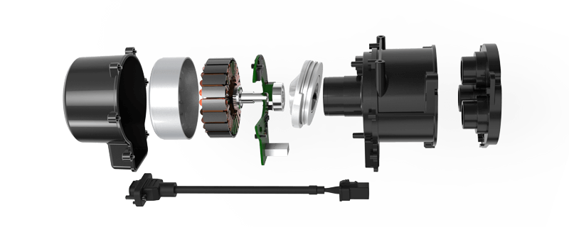
The Basic Components of a Brushless Servo System
A typical brushless servo system consists of the following components:
Brushless Servo Motor (BLDC): The heart of the system, providing motion based on electrical inputs.
Servo Drive or Controller: Manages the current supplied to the motor, executing control algorithms to achieve desired rotor positions or speeds.
Feedback Sensor: Usually an encoders or resolvers that provide real-time rotor position and speed data.
Power Supply: Supplies the necessary electrical energy, often at high voltage and current levels.
A robust control system must interpret feedback data accurately and adjust the inverter signals accordingly, creating a closed-loop control that maintains the intended motion trajectory.
Fundamentals of Brushless Servo Motor Control
Controlling a brushless servo motor requires precise management of its electrical inputs to produce the desired mechanical output. This process involves several key steps:
Position and Speed Feedback Acquisition: Acquiring accurate rotor position and speed data is vital. Encoders or resolvers translate the physical rotation into electrical signals, which are fed into the controller. Modern systems often use high-resolution encoders for fine control.
Control Algorithm Implementation: The core of the control system is the algorithm that determines how to modulate the inverter signals. Common algorithms include Field-Oriented Control (FOC), also known as vector control, and sinusoidal PWM. FOC is particularly popular due to its smooth torque production and high dynamic performance.
Inverter Switching and PWM Modulation: The controller converts the control signals into high-frequency PWM signals that drive the inverter, which switches the voltage on the motor's phases. Proper modulation ensures efficient energy transfer and precise control.
Closed-loop Feedback: As the motor accelerates or changes direction, the system constantly updates its commands based on feedback, maintaining precise control over rotor position, speed, and torque.
Understanding Field-Oriented Control (FOC)
Among control methods, Field-Oriented Control stands out for its sophisticated approach that treats the motor control problem akin to controlling a DC motor within an AC environment. The core idea is to decompose the stator currents into two orthogonal components:
Direct axis (d-axis): Aligns with the rotor magnetic flux; controlling this component manages flux.
Quadrature axis (q-axis): Perpendicular to the flux; controlling this component manages torque.
By transforming the three-phase motor currents into a two-axis system (Clarke and Park transformations), the controller can independently regulate flux and torque, resulting in smooth, precise motion.
Implementing FOC involves several stages:
Sensing rotor position Performing coordinate transformations Calculating appropriate voltage vectors for the inverter Executing PWM modulation sequences
The result is a highly responsive control system capable of precise torque and position control, even at low speeds.
This marks the end of Part 1. Up next, we'll explore the detailed implementation steps for brushless servo motor control, common challenges, and troubleshooting tips.
Leveraging innovations in modular drive technology, Kpower integrates high-performance motors, precision reducers, and multi-protocol control systems to provide efficient and customized smart drive system solutions.
Update:2025-10-15
Contact Kpower's product specialist to recommend suitable motor or gearbox for your product.


