


Looking for a suitable motor?


小编
Published2025-10-15
Imagine the excitement of constructing a robot capable of precise movements, from a simple arm reaching out to an object to a complex drone navigating the skies. At the heart of many of these innovations lies a humble yet powerful component: the servo motor. These compact devices are the backbone of accurate motion control, and understanding how to connect and power them correctly is vital for turning your creative ideas into reality.
In the world of electronics and robotics, nowhere is the connection between hardware and software more critically tested than in the integration of servo motors with microcontrollers like Arduino. The "servo motor Arduino pinout" is more than just a set of wire connections—it's the fundamental blueprint that ensures your project runs smoothly, efficiently, and reliably.
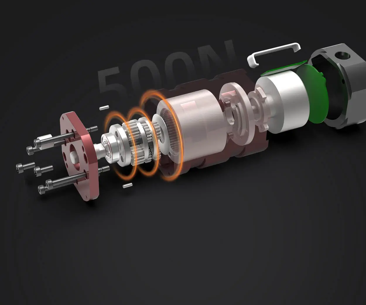
What is a Servo Motor? Before diving into the pinout specifics, it’s helpful to clarify what a servo motor actually is. Unlike standard motors that rotate continuously when powered, servo motors are designed for precise position control. They consist of a small DC motor, a built-in potentiometer (or position sensor), and a control circuit. This design allows you to set a target position, and the servo will adjust its shaft accordingly, holding that position firmly.
Servo motors are categorized primarily into two types: standard servos and continuous rotation servos. The standard servo is what most hobbyists work with for creating robotic arms or pan/tilt mechanisms, while continuous rotation servos operate like regular motors, useful for driving wheels or other continuous movement applications.
The Core Components of a Typical Servo Motor A typical servo motor includes three essential parts linked through its pinout:
Power (Vcc): Usually +5V, supplying the motor and control circuitry Ground (GND): Completing the circuit Signal (PWM control): A Pulse Width Modulated signal that dictates the position or speed
These three pins are usually configured on the servo's connector in a specific order, but variations exist depending on the manufacturer.
Why Understanding the Arduino Pinout Matters Knowing the correct pin connections ensures that your servo receives the proper signals and power, reducing the risk of damage and increasing the reliability of your setup. Miswiring can lead to erratic movements or, worse, permanent damage to your servo or Arduino board.
When you look at the typical "servo motor Arduino pinout," you'll find it straightforward, but it pays to understand what each pin does and how to connect them correctly to your Arduino.
The Standard Servo Pinout Most hobbyist servo motors feature at least three pins, arranged in a specific order:
Vcc (Power): Usually the red wire GND (Ground): Usually the black or brown wire Signal (PWM): Usually the yellow, white, or orange wire
Some servo models might have a fourth, optional pin for additional functions or enhancements, but for standard control, three pins are enough.
Connecting Your Servo to Arduino — a step-by-step overview:
Power Supply: Your servo’s power and ground pins should be connected to the Arduino’s 5V and GND pins respectively. For small projects, Arduino's onboard 5V may suffice, but for larger servos or multiple servos, an external power supply is recommended to prevent voltage dips or overstressing the Arduino.
Signal Pin Connection: Connect the servo's signal wire to one of Arduino's PWM-capable digital pins. Pins 3, 9, 10, and 11 on most Arduino Uno boards are popular choices for servo control because they support PWM signals.
Ensuring Power Stability: If you’re working with multiple servos or high-torque models, consider providing an external power source (like a 5V regulated power supply) and connect its ground to the Arduino ground. This common ground is crucial for signals to be interpreted correctly.
Testing Your Connection Once you wire everything, using an Arduino sketch like the standard Servo.h library example makes it easy to test if everything works correctly. You can write a simple program to rotate the servo from 0 to 180 degrees and back, observing its movement and smoothness.
Here’s a quick snippet to test:
#include Servo myServo; void setup() { myServo.attach(9); // Connect signal pin to Arduino pin 9 } void loop() { myServo.write(0); // Rotate to 0 degrees delay(1000); myServo.write(180); // Rotate to 180 degrees delay(1000); }
If your servo responds correctly, you’re ready for more advanced projects.
Always verify the voltage ratings of your servo. Connecting a 6V or higher servo to 5V may lead to malfunction, while some micro servos are designed to run on 4.8V. Use a dedicated power supply for multiple servos, not the Arduino's 5V pin, to ensure stable operation. Keep your wiring neat and avoid crossing wires to reduce the risk of short circuits.
Understanding Your Servo's Specific Pinout While most servos follow the three-pin standard, it's not universal. Always check your servo's datasheet or manufacturer's documentation for the exact wiring diagram. Some servos might invert the pin order or label their wires differently. Correct identification ensures proper connection and avoids unnecessary troubleshooting.
Looking Ahead In Part 2, we'll delve deeper into configuring your Arduino code, troubleshooting common issues, exploring advanced control techniques like PWM modulation for finer movements, and discussing how servo motor pinouts can vary across different models. Plus, we'll explore some creative projects that harness this fundamental knowledge for amazing robotics and automation applications.
Stay tuned as we unlock the full potential of your servo motors and Arduino!
Leveraging innovations in modular drive technology, Kpower integrates high-performance motors, precision reducers, and multi-protocol control systems to provide efficient and customized smart drive system solutions.
Update:2025-10-15
Contact Kpower's product specialist to recommend suitable motor or gearbox for your product.


