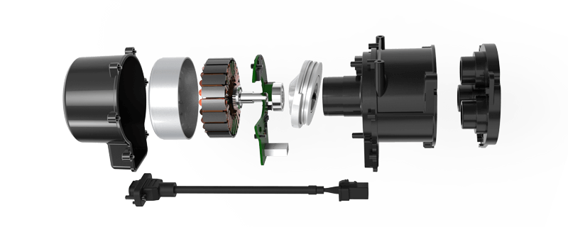
Unlocking Precision: An In-Depth Guide to DC Servo Motor Wiring Diagrams
If you've ever marveled at the seamless movement of industrial robots, CNC machines, or even high-quality drone stabilizers, there's a good chance a DC servo motor is quietly powering their precision. These tiny yet formidable components are the backbone of modern automation, turning electrical energy into controlled rotational motion with remarkable accuracy. But one question often pops up when installing or troubleshooting: How do I properly wire a DC servo motor?

Understanding the wiring diagram of a DC servo motor isn’t just about connecting wires—it's about unlocking the potential for smooth, reliable operation and precise control. So, let’s walk through why wiring matters and how to interpret these diagrams step by step.
What is a DC Servo Motor?
At its core, a DC servo motor is an electric motor equipped with a feedback sensor, typically an encoder, that provides data about the motor’s position, speed, or both. This feedback allows a control system to adjust the motor's operation in real time, achieving exact positioning or speed regulation. Unlike simple DC motors, which spin freely, a servo motor's dynamic precision makes it invaluable in robotics, manufacturing, and automation.
The Essentials of a Wiring Diagram
A wiring diagram for a DC servo motor charting the electrical connections is more than a simple map; it’s a blueprint for performance. It highlights various components involved, such as power supply, control signals, feedback sensors, and protection devices.
Here are some common elements you'll encounter in a typical DC servo motor wiring diagram:
Power Supply Terminals: Usually marked as V+ and V-. These supply the necessary voltage and current. Motor Terminals: The connections feeding the motor coils (often labeled as A+ A-, B+ B- depending on the motor's windings). Encoder or Feedback Device: For position and velocity feedback—these are crucial for accurate control. Control Signal Inputs: Including pulse signals, PWM signals, or analog inputs, which dictate the motor’s commands. Ground Connections: Common reference points for electrical stability.
Types of DC Servo Motors and Their Wiring Needs
Not all servo motors are wired the same. A few common variations include:
Brushless DC (BLDC) Servo Motors: Require electronic commutation, typically wired to three phases (U, V, W) and a dedicated controller. Brushed DC Servo Motors: Usually simpler in wiring, with two power connections and feedback sensor wiring. Coreless and Core-based motors: Differences may influence wiring approach but less so than the motor type itself.
Basic Wiring Principles
Before diving into complex circuits, here's a quick primer—think of wiring like setting up a flow of energy and signals:
Ensure proper power ratings: Voltage and current must match the motor specifications. Reliable connections: Use appropriate gauge wires and secure terminals. Isolate signal wiring: Keep low-voltage control signals separate from high-current power lines to prevent noise. Connect feedback loops correctly: Encoders or sensors need precise wiring for accurate feedback.
Analyzing a Typical DC Servo Motor Wiring Diagram
Suppose you’re faced with a diagram illustrating a brushed DC servo motor with an encoder. It might appear as a series of lines connecting labeled blocks:
One branch runs from a power supply (+V) to the motor's positive terminal. A corresponding line connects the negative terminal to Ground. Encoder signals (like A, B, Z channels) are wired from the encoder to the servo controller. Control signals—such as PWM or velocity commands—are connected to input terminals on the controller.
Understanding this layout is akin to reading a map; it guides your wiring process, ensuring every component receives the correct signals and power. It’s also fundamental to troubleshooting—knowing which wire corresponds to which part can help pinpoint issues like signal loss or power failure.
Safety First
Before beginning any wiring task, remember safety:
Turn off power sources before making connections. Verify voltage and current specifications. Use insulated tools and appropriate personal protection equipment. Double-check connections with a multimeter before powering up.
Choosing the Right Wiring Materials
For optimal performance:
Use wires rated for the current and voltage involved. Employ connectors designed for the application's environment. Consider shielding cable runs to reduce electromagnetic interference, especially in noisy industrial environments.
Stay tuned for the second part, where we will delve into practical wiring steps, troubleshooting tips, and advanced considerations for integrating DC servo motors into various systems. The goal? Empowering you to confidently design, install, and maintain servo motor setups with clarity and skill.
Established in 2005, Kpower has been dedicated to a professional compact motion unit manufacturer, headquartered in Dongguan, Guangdong Province, China.


