


Looking for a suitable motor?


小编
Published2025-10-15
Certainly! Here’s the first part of the soft article on “how to wire a servo motor,” crafted to be engaging and informative. I will provide Part 1 and then follow up with Part 2.
Getting Started: Understanding Your Servo Motor
Before diving into wiring, it’s essential to understand what a servo motor is and why wiring correctly matters. A servo motor is a compact rotary actuator that allows precise control of angular position. Unlike simple DC motors, servo motors include a built-in control circuit—typically with sensors and feedback mechanisms—that allows exact position control through PWM (pulse-width modulation) signals.
Servo motors are staples in projects ranging from remote-controlled cars to robotic arms and CNC machines. Their inclusion in a project hinges on correct wiring, which ensures they operate reliably and respond accurately to control signals.
Identifying the Components and Pins
Most servo motors share common features:
Power (V+): Usually connected to a positive DC voltage, often 4.8V to 6V for standard hobby servos. Ground (GND): Connected to the negative terminal of your power supply. Signal (PWM control line): Receives the control signals that dictate the servo’s position.
Standard servo cables are typically three-wire:
Red: Power (V+) Black or Brown: Ground (GND) Yellow, White, Orange: Signal (control)
It’s a good idea to check your specific servo's datasheet or label because wire colors can sometimes vary depending on the manufacturer or servo model.
Preparation before wiring
Ensure your power supply can handle the current draw of the servo during operation, especially if you plan to run multiple servos simultaneously. Servos can draw substantial current, and under-powered setups can lead to inconsistent responses or damage.
Gather your tools and materials:
Servo motor Power supply (battery or regulated power supply) Microcontroller or control board (like Arduino, Raspberry Pi, etc.) Connecting wires and jumpers Breadboard or soldering tools (if needed)
Step-by-Step Wiring Process
Now, let's move through the basic wiring steps for connecting a typical hobby servo to your microcontroller:
Identify the wires on your servo. Refer to the datasheet or labeling.
Connect the Power Wire: Connect the red wire to your power source’s positive terminal (typically +5V). Ensure the power source can supply sufficient current.
Connect GND: Connect the black or brown wire to the ground of your power supply and your control board.
Connect the Signal Pin: Connect the control wire (yellow/white/orange) to one of your microcontroller’s PWM-capable pins. For Arduino, pins like 9, 10, or 11 are common choices.
Verify Connections: Double-check all connections to avoid shorts or incorrect wiring.
Power considerations and precautions
Using a common ground between your power supply and control board is crucial to ensure proper communication. Avoid powering the servo directly from a microcontroller’s 5V pin if your servo demands more current; instead, power the servo directly from a suitable power source. When in doubt, use a dedicated power source for the servo, and incorporate a voltage regulator if needed.
Once wired, upload a simple control sketch (if using Arduino), such as the basic sweep example, to test the servo movement. Observe if it moves smoothly across its range. If not, re-check your wiring and power supply.
Does the servo twitch or jitter? The power supply might be insufficient or noisy. No movement? Validate your signal connection and verify your control code. Overheating or stalling? You may be drawing too much current or providing incorrect voltage.
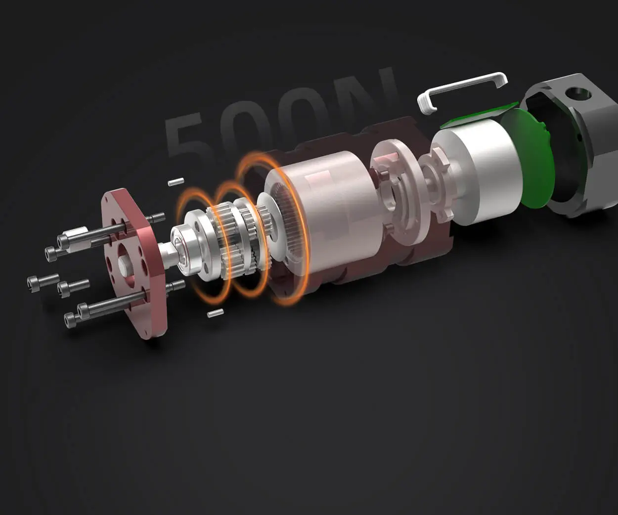
Leveraging innovations in modular drive technology, Kpower integrates high-performance motors, precision reducers, and multi-protocol control systems to provide efficient and customized smart drive system solutions.
Update:2025-10-15
Contact Kpower's product specialist to recommend suitable motor or gearbox for your product.


