


Looking for a suitable motor?


小编
Published2025-10-15
Unlocking Precision: A Deep Dive into Servo Motor Arduino Datasheets
In the vibrant world of electronics and robotics, servo motors stand out as a cornerstone component—particularly when precision, control, and repeatability are paramount. Whether you're crafting a robotic arm, an autonomous vehicle, or a home automation system, understanding the ins and outs of servo motors is crucial. And at the heart of this understanding lies the datasheet—an indispensable document that can make or break your project.
Before diving into datasheets, let's clarify what a servo motor truly is. Unlike simple DC motors, servo motors are designed to provide precise control of angular position, velocity, and acceleration. They typically comprise a small motor coupled with a feedback device, such as a potentiometer or an encoder, along with control circuitry—often integrated into a compact housing.
This combination allows for closed-loop control, meaning the motor's position is constantly monitored and adjusted, providing remarkable accuracy. Servo motors are prevalent across robotics, RC (radio-controlled) hobbies, CNC machinery, and automation systems.
Why Use Arduino with Servo Motors?
Arduino microcontrollers are an accessible, user-friendly platform that democratized electronics hobbyism. What's more satisfying than connecting a servo motor to an Arduino, writing a simple script, and seeing a robotic arm move precisely according to your commands?
The synergy between Arduino and servo motors hinges heavily on understanding the servo's specifications—which are outlined in its datasheet. It allows you to match the right servo to your project requirements, avoid pitfalls like overheating or insufficient torque, and fine-tune your control systems.
Decoding the Servo Motor Datasheet
A datasheet isn't simply a list of numbers—it's a detailed map of what the motor can do and how it behaves under various conditions. To leverage its full potential, you need to become fluent in reading and interpreting the data.
Here's an overview of the key sections you’ll typically find in a servo motor datasheet:
Electrical Specifications Mechanical Characteristics Control and Power Input Performance Data Environmental Conditions Pinout and Wiring Diagrams Operating and Storage Conditions Additional Features and Certifications
Electrical Specifications
This section tells you what voltages the servo can operate within, along with the expected current draw. Typically, you’ll see a working voltage range, often between 4.8V to 6V for standard servos, and sometimes higher for high-torque models.
The stall current—the maximum current the servo draws when prevented from moving—is critical because your power supply must be capable of delivering this current without voltage drops. Ignoring this can lead to servo resets or damage.
Mechanical Characteristics
This area details the physical limits and performance. Key parameters include:
Torque: Usually specified in kg·cm or oz·in, indicating how much force the servo can exert at a specific arm length.
Speed: Often given as seconds per 60° or 360°, indicating how quickly the servo responds to position commands.
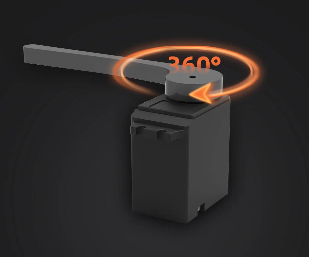
Rotation Range: Most servo motors have a rotational limit, often from 0° to 180°, but some are capable of continuous rotation.
Weight and Size: Vital for integration into your project, especially if space and weight are constraints.
Understanding the control signals is essential. Standard hobby servos are controlled via PWM signals, typically with a pulse width between 1ms and 2ms, corresponding to 0° to 180° positions.
The datasheet often shows the recommended control pulse frequency (usually 50Hz). It may also specify the minimum and maximum pulse durations.
This section gives real-world expectations under typical operating conditions. For example, the servo's response time at a given load, repeatability (how accurately it returns to a commanded position), and durability (number of operational cycles).
Temperature ranges, humidity tolerances, and protection levels (like IP ratings) help determine where the servo can operate reliably.
Pinout and Wiring Diagrams
A clear mapping of the terminal connections simplifies integration. It indicates which pins are power, ground, control signal, and sometimes optional feedback or sensor outputs.
That covers roughly half of the in-depth content about servo motor datasheets and their critical elements. Understanding these sections helps you select and control servos effectively, avoiding unexpected failures and ensuring your project’s success.
Kpower has delivered professional drive system solutions to over 500 enterprise clients globally with products covering various fields such as Smart Home Systems, Automatic Electronics, Robotics, Precision Agriculture, Drones, and Industrial Automation.
Update:2025-10-15
Contact Kpower's product specialist to recommend suitable motor or gearbox for your product.


