


Looking for a suitable motor?


小编
Published2025-10-15
Unlocking Precision: A Comprehensive Guide to Servo Motor Pin Configuration
In the world of robotics, automation, and hobby projects, servo motors stand out as the versatile workhorses of precise movement. Whether you’re building a robotic arm, RC vehicle, or automated system, understanding how to correctly connect and configure your servo motor is fundamental. At the heart of this lies what might seem like simple wiring but is, in reality, a crucial aspect that determines your project's success or failure — the servo motor pin configuration.
The Basics of Servo Motors
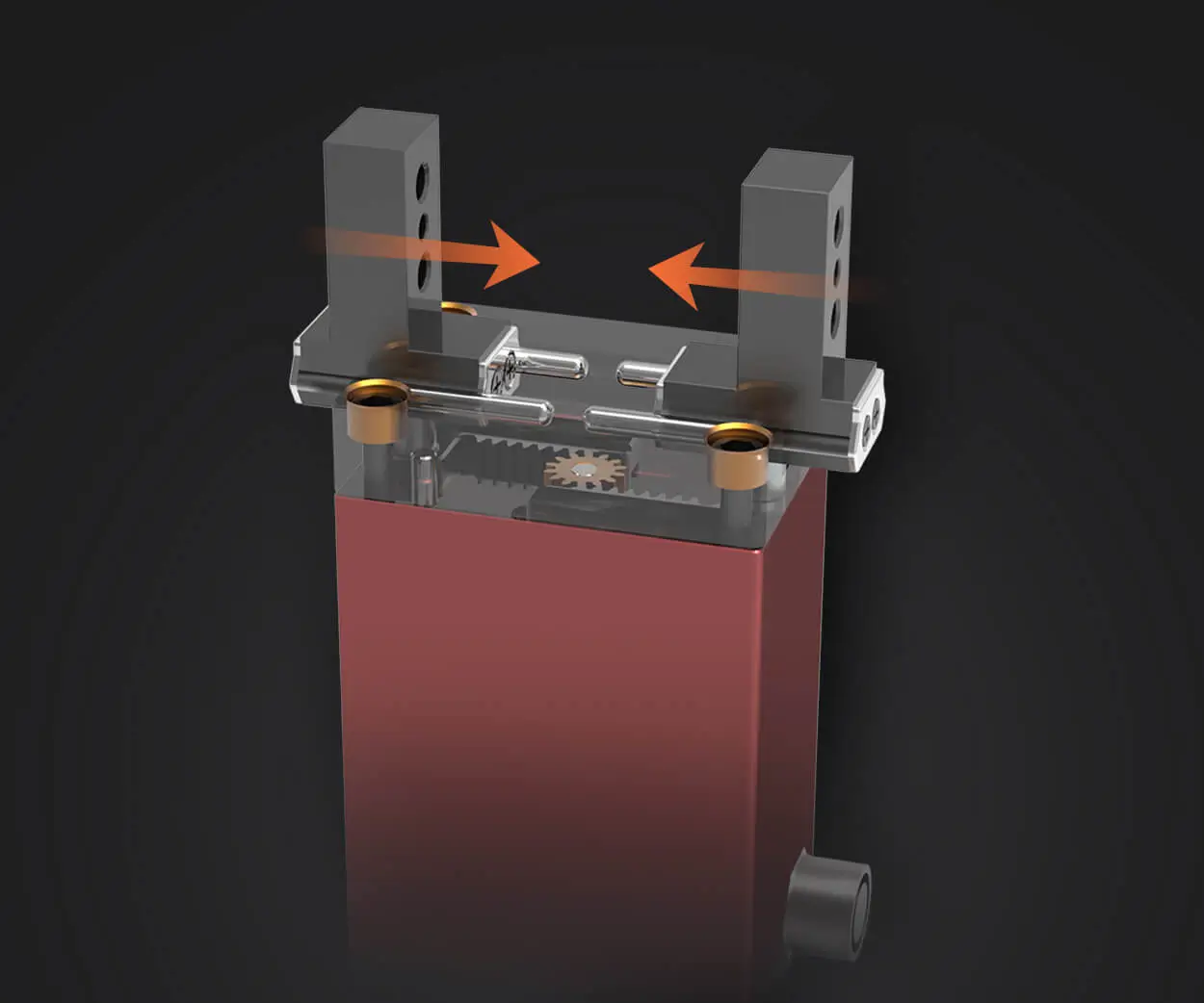
Before diving into pin specifics, let’s clarify what a servo motor is. Unlike standard DC motors that rotate continuously, servo motors are designed for precise control of angular position, velocity, and torque. Their internal architecture includes a small motor, a gear train, a potentiometer (or other position sensor), and a control circuit. The control circuit interprets a PWM (Pulse Width Modulation) signal to adjust the motor’s position accordingly.
Knowing this, the wiring and pin configuration become vital for ensuring the controller correctly communicates with the servo motor. Most commonly, servo motors come with a cable containing three wires: power (VCC), ground (GND), and signal. However, the specifics can vary based on the manufacturer, motor type, and application.
Common Servo Motor Pinouts
While there is no universal standard for all servo pin configurations, there are common patterns widely adopted:
Red wire: Power supply (+V or VCC) Black or Brown wire: Ground Yellow, White, or Orange wire: Signal input/output
This configuration is most typical in hobby servos used in RC vehicles and robotics. Understanding these color conventions helps prevent wiring mistakes that can damage the servo or your control system.
Pin Configuration Variations
Despite the typical three-wire setup, some servo motors incorporate additional pins or different arrangements:
4-pin servos: Some advanced models include a sensor or feedback pin, often used in industrial or custom applications. Multipurpose pins: Certain servos designed for industrial automation could include an emergency stop pin or other control signals. Differential wiring: Though rare, some specialty motors may employ differential signaling to reduce noise and interference.
Whenever you're working with a new servo motor type, always consult the datasheet or manufacturer's documentation. It provides definitive pinout information essential for safe and effective wiring.
Reading the Datasheet: The Key to Correct Pin Usage
Datasheets are your best friend when it comes to understanding servo pin configurations. They typically contain diagrams showing pin layout, voltage ratings, current draw, and connection instructions.
Key aspects to look for include:
Pin numbering: Which pin is assigned to power, ground, and signal. Voltage specifications: Most hobby servos operate around 4.8V to 6V, but industrial ones might have different requirements. Pin functions: Clarifies if any pins have secondary functions such as feedback, sensor output, or control signals.
By adhering to the manufacturer's recommended wiring diagram, you ensure your servo operates efficiently and remains protected from electrical mishaps.
Wiring Tips for Safe and Effective Connections
Proper wiring is not just about connecting pins; it’s about ensuring reliability and longevity for your servo system. Here are some practical tips:
Use appropriate wire gauges: Thin wires may cause voltage drops, affecting performance. Secure connections: Use crimp connectors or solder joints for low-resistance, durable connections. Avoid wire tangling: Prevent unnecessary stress on the servo to avoid damaging internal components. Implement power filtering: Use decoupling capacitors (e.g., 100uF electrolytic capacitor) across power and ground to smooth out voltage fluctuations that can cause jittering or erratic movement.
Since servo motors draw substantial current, especially under load, proper power management is vital:
Separate power supply: Use a dedicated power source for servo motors when possible to avoid introducing noise into your control board. Voltage regulation: Ensure voltage stays within specified limits to prevent overheating or damage. Backup plans: Incorporate fuses or current limiting circuits to protect your system during overloads.
By respecting these wiring and powering best practices, you'll maximize servo performance and lifespan.
Troubleshooting Common Wiring and Pin Configuration Issues
Misconnection or incorrect pin identification can lead to a host of problems: servo jitter, inconsistent movement, or complete failure to respond. Common issues include:
Reversing power and ground: Can damage the servo internally. Incorrect signal polarity: Prevents the servo from interpreting commands properly. Using incompatible voltage levels: Leads to overheating or fried internal components.
If issues arise, double-check your wiring against the datasheet, confirm your power source stability, and test the signal line with a multimeter or oscilloscope if available.
Advanced Pin Configurations and Customizations
Moving beyond basic wiring, many professional or custom servo applications involve additional pin configurations to achieve specific control, feedback, or integration goals.
In industrial or high-precision applications, servos may include feedback pins providing position, velocity, or torque data. Connecting these pins to microcontrollers or PLCs allows for closed-loop control systems that regulate behavior dynamically.
Type of feedback: Analog voltage, PWM signals, or digital signals. Connection considerations: Often require dedicated signal conditioning circuits or special interface modules.
Adding feedback pins expands the scope of your project, enabling exact positioning, fault detection, and even predictive maintenance.
Digital vs. Analog Servos
The pin configuration can also vary between digital and analog servos:
Analog servos: Usually have a simple three-pin connection as described earlier. Digital servos: May include additional pins for improved communication, firmware updates, or serial interface options.
Understanding these differences ensures that your wiring matches the servo’s specifications and capabilities.
Toggle and Control Pins in Industrial Servos
High-end industrial servos sometimes boast multiple control pins, including:
Enable/Disable: Controls power to the motor. Direction control: For adjusting rotation direction. Brake control: Engages or releases brakes for positional holding.
These pins often operate at different voltages or signal levels, demanding careful wiring and logic level considerations.
Choosing the Right Connector and Cable
A critical aspect of wiring is selecting suitable connectors that suit your environment:
Dupont connectors: Common in hobby projects, easy to connect/disconnect. Molex or JST connectors: Provide more secure, weather-resistant connections for embedded or outdoor setups. Custom connectors: For industrial applications, tailor-made connectors help reduce tampering and accidental disconnection.
Cable length and shielding are also vital to prevent signal degradation, especially when operating in electrically noisy environments.
Practical Tips for Wiring Complex Servo Systems
Plan your wiring layout: Avoid crossing wires unnecessarily; keep power and signal lines separate to minimize interference. Label connections: For troubleshooting and easy modifications. Test incrementally: Connect power first, test basic operation, then add signal control. Maintain proper grounding practices: Good grounding reduces noise and improves signal clarity.
Part 1 concludes here, setting the foundation for more advanced configurations and troubleshooting techniques that will be explored in Part 2, including integration tips, common pitfalls, and custom wiring solutions for specialized servo applications. Stay tuned for an in-depth dive into optimizing your servo motor pin configuration for maximum performance.
Established in 2005, Kpower has been dedicated to a professional compact motion unit manufacturer, headquartered in Dongguan, Guangdong Province, China.
Update:2025-10-15
Contact Kpower's product specialist to recommend suitable motor or gearbox for your product.


