


Looking for a suitable motor?


小编
Published2025-10-15
Embarking on Your Robotics Journey: Understanding the Basics of Servo Motors and Arduino
Imagine crafting a robot arm that picks up objects, a camera that precisely pans across a scene, or an automated model that moves with accuracy and grace. At the heart of many such projects lies a small but mighty component: the servo motor. Its ability to rotate to a specific position based on electrical signals makes it indispensable in robotics, automation, and even hobbyist projects.
But to unlock the full potential of a servo motor, you need more than just its mechanical prowess—you need an efficient and reliable circuit that signals it precisely when and how to move. That’s where Arduino, the renowned open-source microcontroller, comes into play. Combining a servo motor with an Arduino is a common starter project that unlocks countless possibilities in automation and robotics.
Understanding Servo Motors
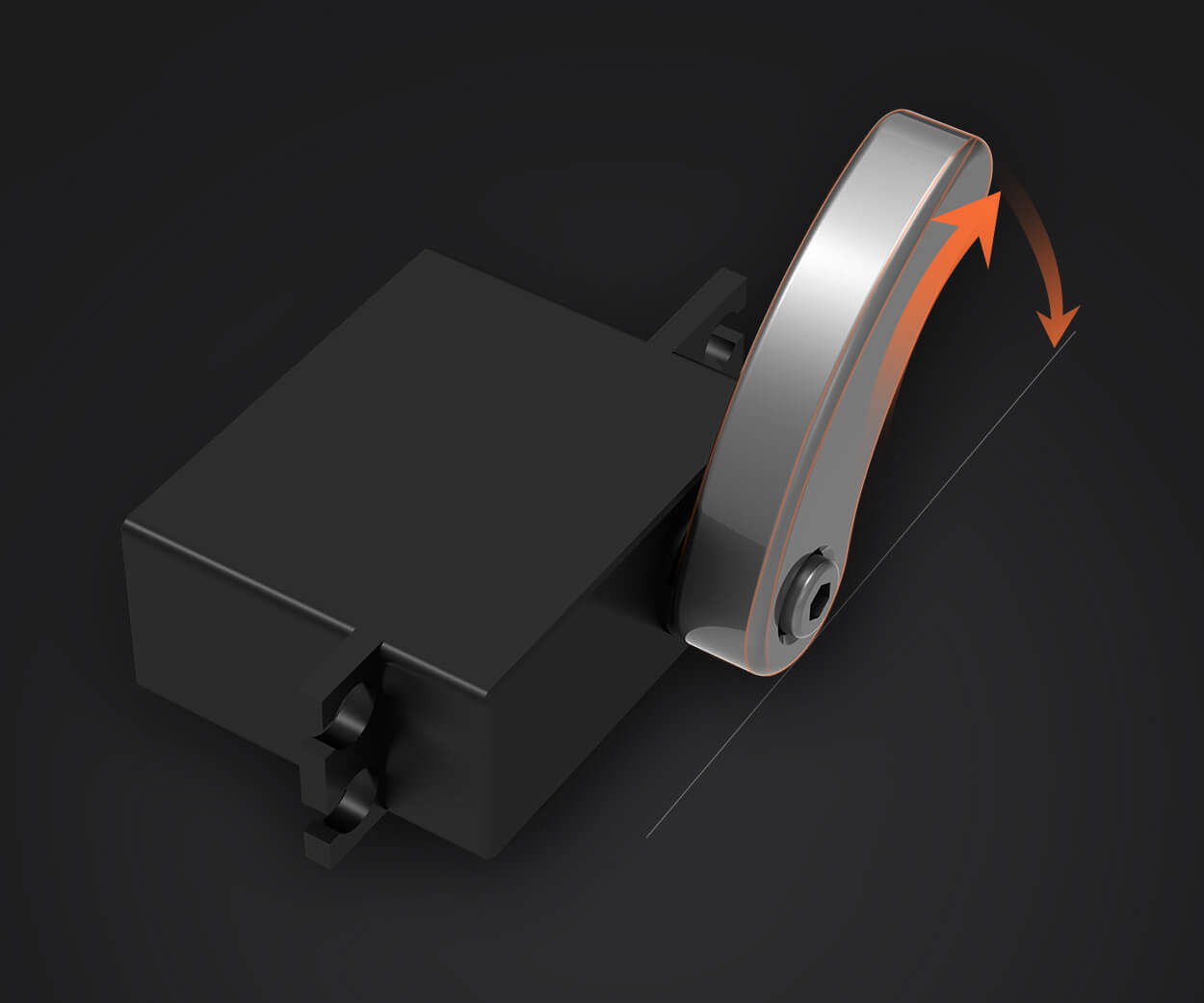
A servo motor isn’t your average motor. It’s designed for precise control of angular or linear position, velocity, and acceleration. Unlike conventional motors, which rotate continuously when powered, servos are capable of holding a position or moving to a specific one, based on control signals.
Most hobbyist servo motors—like the MG996R or SG90—operate using a pulse-width modulation (PWM) signal. The PWM signal determines the position of the servo shaft. For example, a pulse of 1 millisecond might turn the servo to one extreme, while a pulse of 2 milliseconds moves it to the other extreme. The control signal repeats numerous times per second to maintain or change the position as needed.
Arduino’s simplicity, flexibility, and extensive community support make it the perfect choice for controlling servo motors. It can generate accurate PWM signals, read sensor data, and execute complex logic, all in a compact package.
Arduino board (Uno, Nano, Mega, etc.) Servo motor (e.g., SG90, MG996R) Power supply for servo (usually 5V, but some larger servos require dedicated power) Connecting wires (jumper cables) Breadboard (optional, for prototyping) Resistors, if needed for specific control or feedback
Building the Circuit: The Core Concept
At the foundation of controlling a servo motor with Arduino is understanding the key connections. The circuit needs to provide the power supply to the servo, connect the control signal to a PWM-capable pin on the Arduino, and ensure grounding is shared for stability.
The Basic Circuit Diagram
Power Supply Connect the positive terminal of your power source (typically 5V) to the servo’s power (Vcc) pin. Connect the ground (negative terminal) of your power source to both the Arduino GND and servo GND pins. Control Signal Connect the servo’s signal (control) pin to one of the Arduino’s PWM-capable digital pins, like pin 9 or 10. Grounding Confirm that the Arduino GND and the servo GND are connected together to prevent voltage differences. Additional Considerations For high-torque or high-current servos, a separate power supply is recommended—never power the servo directly from the Arduino’s 5V pin alone. Always check the servo specifications and power ratings to avoid damage.
This forms the core of your circuit. It’s simple, yet powerful enough to control the servo's angular position through code.
From Diagram to Reality: Assembling Your Servo Control Circuit
Once you understand the basic connections, the next step is to physically assemble your circuit, ensuring all components are correctly wired for safe and reliable operation.
Prepare Your Components Gather your Arduino, servo motor, power supply, and jumper wires. Make sure your servo’s specifications match your power source; for example, some larger servos may need a 6V power supply instead of 5V. Connecting Power and Ground Connect the positive terminal of your external power supply to the servo's Vcc (red wire typically). Connect the negative terminal to both the Arduino GND and servo GND pin. This common ground ensures a stable reference point across your circuit, minimizing erratic servo movements. Connecting Control Signal Plug the servo's control (signal) wire—usually yellow or white—into a PWM capable digital pin on the Arduino, such as pin 9. Testing the Circuit Power on your Arduino and external power. Confirm all connections are secure. Use a multimeter to check voltage levels if needed. Avoiding Common Pitfalls Never power high-torque servos solely from the Arduino’s 5V pin; always use an external power source for larger servos. Make sure the servo’s GND and Arduino GND are connected. Keep wiring neat and secure to prevent shorts or intermittent connections.
Programming Your Arduino: Control with Code
Having assembled your circuit, the next step involves coding. With the Arduino IDE, you can write a sketch to send PWM signals that control the servo’s position.
#include Servo myServo; void setup() { myServo.attach(9); // Attach servo control to pin 9 } void loop() { for (int pos = 0; pos <= 180; pos += 1) { myServo.write(pos); // Go from 0° to 180° delay(15); // Wait for the servo to reach the position } for (int pos = 180; pos >= 0; pos -= 1) { myServo.write(pos); // Return from 180° to 0° delay(15); } }
This simple code moves the servo smoothly back and forth between 0 and 180 degrees. It’s a foundation for more complex movements and can be integrated with sensors, buttons, or remote controls for interactive projects.
Expanding Your Circuit and Project
Once you’re comfortable with basic control, you can explore more complex setups:
Multiple Servos: Use libraries and multiple PWM pins. Sensor Integration: Use ultrasonic sensors, light sensors, or accelerometers to dynamically control servo movements. Wireless Control: Incorporate Bluetooth, Wi-Fi, or RF modules for remote operation. Feedback Systems: Use potentiometers or encoders for closed-loop control to improve precision.
Servo jittering: Check your power supply. An underpowered servo can jitter or stop. No movement: Confirm your code uploads correctly and the servo is connected to the right pin. Overheating: High-torque servos draw more current; consider cooling or power management. Unexpected behavior: Ensure GNDs are shared and connections are secure.
Having discussed the foundational aspects—how to wire your servo with an Arduino, assemble the circuit, and write basic code—you’re well on your way to building sophisticated robotic systems. Next, explore advanced control techniques, sensor feedback, and automation to elevate your projects to new heights. Whether for hobby or professional pursuits, mastering the circuit diagram of servo motors with Arduino opens endless doors to innovation.
Kpower has delivered professional drive system solutions to over 500 enterprise clients globally with products covering various fields such as Smart Home Systems, Automatic Electronics, Robotics, Precision Agriculture, Drones, and Industrial Automation.
Update:2025-10-15
Contact Kpower's product specialist to recommend suitable motor or gearbox for your product.


