Unlocking the Power of Servo Motors with Arduino: The Ultimate Wiring Guide
Whether you're a seasoned hobbyist or an enthusiastic beginner, integrating servo motors into your Arduino projects opens a world of possibilities—robot arms, remote-controlled vehicles, camera gimbals, and more. But before you dive into programming your servo motors, one foundational step is understanding how to wire them correctly. Proper wiring is key to ensuring your motors perform reliably and without damage.

In this guide, we'll walk through the essential theory behind servo motor wiring and give you step-by-step instructions on how to connect them to your Arduino, plus tips to troubleshoot common issues. Let's start by demystifying what a servo motor is and why wiring matters.
What Is a Servo Motor?
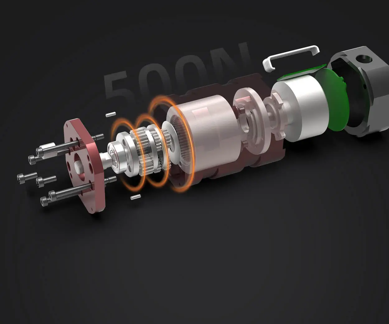
A servo motor isn't just any motor. It's a device designed to precisely control angular or linear position, velocity, and acceleration. The most common servo used in hobby electronics and robotics is the "servo motor" that typically features a small motor, a gear train, a potentiometer (for position feedback), and an electronic circuit for control.
A standard hobby servo usually has three wires:
Power (Vcc): Usually red, supplies voltage (commonly 5V). Ground (GND): Usually black or brown, completes the circuit. Signal (PWM): Usually yellow or white, carries the control pulse.
The control signal is a PWM (Pulse Width Modulation) signal that tells the servo what position to move to.
Essential Wiring Components and Tools
Before starting, gather the following:
Arduino board (Uno, Mega, etc.) Servo motor (popular models include SG90, MG90, etc.) Jumper wires (male-to-male is common) Breadboard (for prototyping) Power supply (if controlling multiple servos or heavy loads) Multimeter (helpful for troubleshooting)
Wiring Basics: Connecting a Single Servo to Arduino
Let’s lay out the precise steps for wiring a single servo motor:
1. Power and Ground Connections
Connect the red wire (Vcc) of the servo to the Arduino's 5V pin. Note: Some servos draw substantial current; if you experience resets or erratic behavior, power the servo separately with an external power supply (more on this later). Connect the black/brown wire (GND) to one of Arduino's GND pins.
2. Signal Connection
Connect the yellow/white wire (Signal) to one of the Arduino's PWM-capable pins. Commonly used pins: 3, 5, 6, 9, 10, 11 on Arduino Uno. For simplicity, let's use pin 9.
3. Power Considerations
While powering the servo from the Arduino's 5V seems straightforward, it's often insufficient for multiple servos or high-torque models. The servo's current demand may exceed the Arduino's onboard regulator capacity, leading to voltage dips or resets.
Best practice: Use an external power supply, such as a 4.8V–6V battery pack, to power the servo. Connect the positive terminal of the battery to the servo's Vcc wire, the negative terminal to GND, and connect the GND of the external power supply to the Arduino GND to establish a common ground.
Advanced Wiring Techniques and Troubleshooting
Now that the basic wiring setup is clear, let's explore more advanced considerations to make your servo projects robust and responsive.
4. Powering Multiple Servos
When controlling more than one servo, each motor's current draw adds up. Using a single power source is recommended but requires caution:
Use a dedicated power supply capable of delivering sufficient current (e.g., 2A or more for several servos). Connect all servo grounds to the power supply's ground and also to the Arduino GND for a common reference. Never power servos directly from the Arduino 5V pin if they require more than about 500mA – risk of damaging the board.
5. Using a Breadboard vs. Direct Wiring
Breadboards are excellent for prototyping but might introduce additional voltage drops. For stable operation, especially with multiple servos, soldered connections or dedicated power rails sourced from a stabilized power supply are preferable.
Wiring Safety Tips
Always verify wiring before powering up. Keep signal wires away from power wires to prevent interference. Use ferrite beads or shielded cables if you encounter electrical noise or jitter.
Connecting the Signal Wire: PWM Control
The control signal wire receives PWM signals that command the servo to specific positions. The Arduino's Servo library makes this straightforward, but neat wiring ensures signals stay clean and responsive.
Connecting the Signal Wire
Use a jumper wire from Arduino pin 9 (or your chosen pin) to the servo's signal wire. Keep the wire as short as feasible to reduce electromagnetic interference.
Programming the Servo
Once wired, you’ll write code using the Servo library in Arduino IDE:
#include Servo myServo; void setup() { myServo.attach(9); // Pin connected to signal wire } void loop() { myServo.write(90); // Moves servo to 90 degrees delay(1000); myServo.write(0); // Moves servo to 0 degrees delay(1000); }
Upload this code, and your servo should oscillate between positions. Always check that the servo moves smoothly and without jitter.
Troubleshooting Common Wiring Issues
Servo not moving: Double-check connections, especially power and GND. Confirm signal wire is connected to a PWM pin. Jittery or unresponsive movement: Ensure signal wire is not picking up noise; add a capacitor (e.g., 100μF) across Vcc and GND at the servo power line. No movement: Verify code logic, check power supply, ensure servo is functional.
Final Tips for Reliable Servo Wiring
Use color Coding: red for Vcc, black/brown for GND, yellow/white for Signal. Maintain neat wiring to avoid accidental disconnections. Use a multimeter to verify voltages before connecting to the Arduino. Consider adding a small decoupling capacitor (0.1μF ceramic) across the servo power lines to reduce electrical noise.
Getting your servo wiring right is foundational to successful Arduino robotics projects. Master these principles, and you'll pave the way for smoother control and more complex creations.
Stay tuned for Part 2, where we dive deeper into troubleshooting, advanced wiring configurations, and best practices for professional-grade projects!
Kpower has delivered professional drive system solutions to over 500 enterprise clients globally with products covering various fields such as Smart Home Systems, Automatic Electronics, Robotics, Precision Agriculture, Drones, and Industrial Automation.


