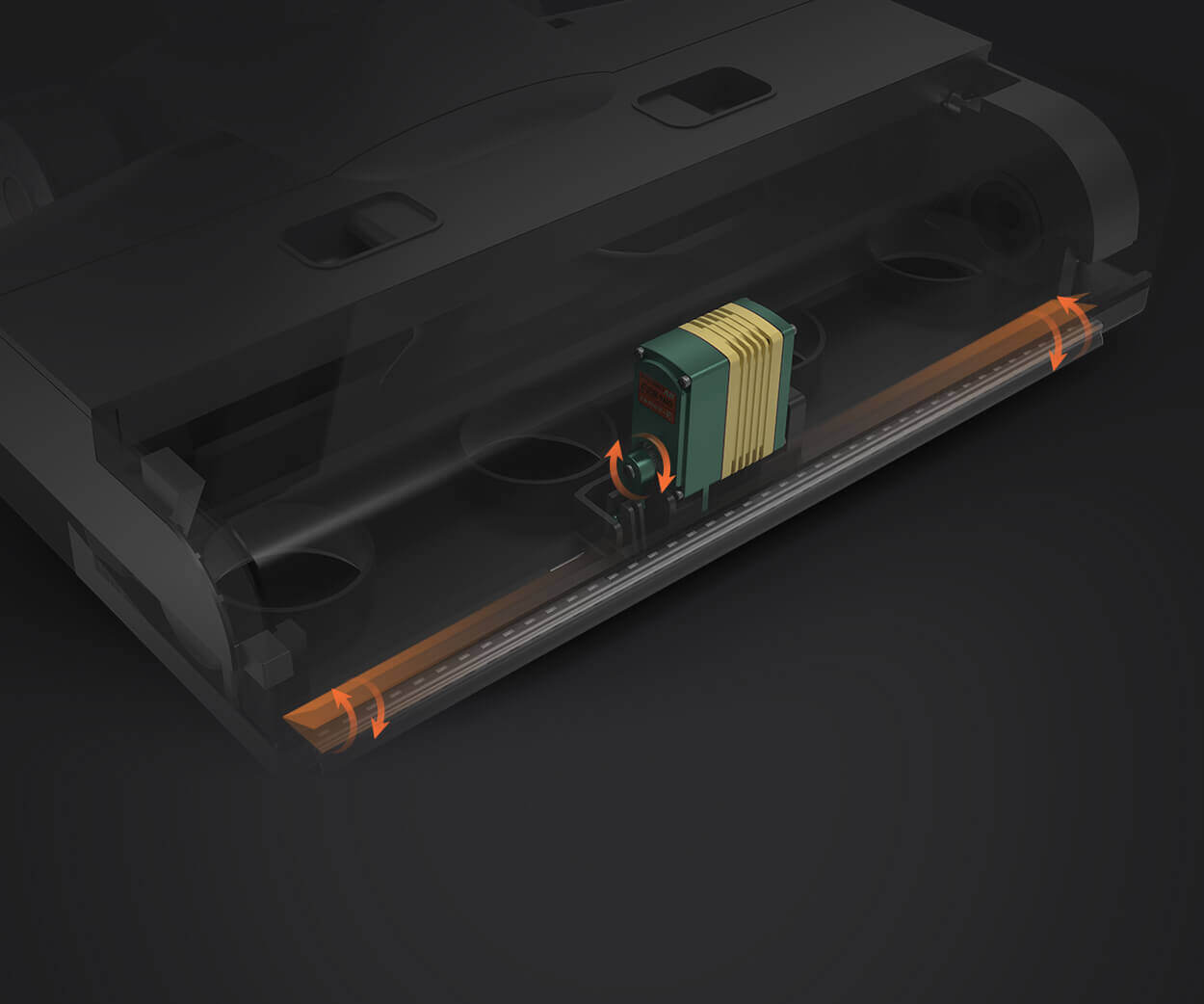
Unveiling the Power Behind Precision: An Introduction to DC Servo Motors
In the world of automation, robotics, and precise control systems, few components are as pivotal as the DC servo motor. These compact yet powerful devices are the backbone of systems that demand exact positioning, rapid responsiveness, and reliable performance. Understanding how a DC servo motor works isn't just an academic curiosity—it’s a key to unlocking innovation across countless industries.

At their core, DC servo motors are specialized types of direct current motors designed for controllable motion and precise positional feedback. Unlike regular motors that spin freely once powered, servo motors are part of a closed-loop control system. This setup continuously monitors and adjusts the motor's position, speed, or torque to meet specific commands. It’s this feedback mechanism that elevates a simple motor into a finely-tuned instrument of precision.
The Basic Architecture of a DC Servo Motor
A typical DC servo motor comprises a stationary part called the stator, which houses the motor’s core components, and a rotating part called the rotor or armature. The rotor is mounted on a shaft, which transmits mechanical motion. Inside the motor, copper windings or coils are wrapped around the rotor, and magnets are placed in the stator to generate magnetic fields.
The design intricacy of a servo motor allows it to produce high torque at low speeds and respond swiftly to control signals—qualities essential for applications like robotic arms, camera gimbals, or antenna positioning systems.
Key Components and Their Roles
Armature (Rotor): The part that rotates, usually embedded with windings or coils. When current flows through these coils, it creates magnetic fields that interact with the stator’s magnetic fields, causing rotation.
Stator Magnets: Permanent magnets or electromagnetic coils that produce a magnetic field, which interacts with the armature’s magnetic field.
Feedback Device: A sensor such as an encoder or resolver detects the actual position of the rotor. This is critical for closed-loop control.
Control Circuit: The brain of the system, often a specialized servo amplifier or motor driver, which compares the feedback signal to the desired command and adjusts the current accordingly.
How the System Is Controlled
In a control environment, a command signal—often a voltage—sets the target position or speed. The feedback device continually relays the current position of the rotor back to the controller. The comparator then assesses the difference, or error, between the target and actual positions.
If there's a discrepancy, the control circuit adjusts the current supplied to the armature coils, generating a magnetic force that pushes the rotor toward the commanded position. This process repeats rapidly, ensuring the rotor remains aligned with the intended position with remarkable accuracy.
The Role of the PWM Signal and the PID Controller
In advanced servo systems, pulse-width modulation (PWM) signals are used to regulate the current supplied to the motor. By rapidly switching the power on and off, and adjusting the duty cycle, the system finely tunes the motor's operation.
The PID (Proportional-Integral-Derivative) controller is often incorporated into the control system. It mathematically processes the error signal to produce control actions that minimize overshoot and stabilize the system. The proportional component responds to the current error, the integral accounts for accumulated past errors, and the derivative anticipates future errors, creating a balanced and responsive control loop.
Power Supply and Drive Mechanisms
Powering the servo motor requires a suitable drive mechanism capable of handling rapid changes in current. Often, a dedicated servo amplifier or driver circuit is used. It ensures that the motor receives the correct voltage and current, enabling precise control without risking damage from overloads.
In essence, the motor's internal electronics interpret the control signals and translate them into physical movement, closing the feedback loop. This seamless interaction of hardware and software makes DC servo motors extraordinarily precise and adaptable.
Applications of DC Servo Motors
DC servo motors find applications across a broad spectrum:
Robotics: For precise joint movement and orientation. Aerospace: Controlling aircraft instrument gimbals. Automotive: Power steering and automated systems. Manufacturing: CNC machines that require exact tool positioning. Consumer electronics: Camera autofocus systems and drones.
In the next part of this article, we will delve into the detailed working mechanism, including the electromagnetic principles that govern operation, the role of sensors and control algorithms, as well as emerging trends enhancing the capabilities of DC servo motors.
Leveraging innovations in modular drive technology, Kpower integrates high-performance motors, precision reducers, and multi-protocol control systems to provide efficient and customized smart drive system solutions.


