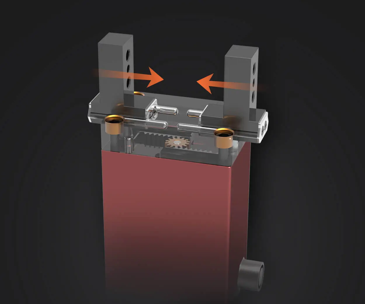
Certainly! Here’s the first part of the soft article based on the theme "Schematic Diagram of AC Servo Motor."

Imagine a conductor orchestrating a symphony, each note perfectly in harmony, creating a melody that moves gracefully through space. Similarly, an AC servo motor functions as a conductor—a powerhouse that enables precise, controlled movements in robotics, manufacturing, aerospace, and countless other sectors. To truly appreciate its complexity and efficiency, one must delve into the schematic diagrams that serve as the blueprint for these sophisticated devices.
At its core, an AC servo motor is designed to produce highly accurate rotational or linear motion. Unlike simple motors that run at full speed once powered, servo motors are equipped with control systems that enable them to position, velocity, or torque with exceptional precision. The schematic diagram of an AC servo motor offers a window into this inner universe, revealing the intricate interplay of electrical and mechanical components.
Understanding the Basic Architecture
When you look at a schematic of an AC servo motor, what you’re essentially seeing is a map of the various interconnected parts that turn electrical signals into precise mechanical movement. Broadly, these systems comprise three primary sections:
Power Supply and Drive Circuitry Feedback Control Loop The Motor Itself
Let’s start at the foundation—the power supply and drive circuitry. AC servo motors typically operate on three-phase AC power, delivered through a variable frequency drive (VFD). This drive acts as the brain that controls the voltage, current, and frequency supplied to the motor. The schematic diagram visually maps out components like rectifiers, inverters, filters, and converters—each playing a crucial role.
The rectifier converts incoming AC power into DC, creating a stable voltage source. Then, the inverter takes this DC input and synthesizes an AC output with adjustable frequency and amplitude. By modulating these parameters, the inverter effectively controls the speed and torque of the motor. The components involved include IGBTs (Insulated Gate Bipolar Transistors) or MOSFETs, which switch rapidly to create the desired waveform.
Feedback and Sensor Integration
One of the key features that set AC servo motors apart from regular motors lies in their feedback systems. The schematic diagram vividly displays sensors—most commonly encoders—that continuously monitor the motor's shaft position, speed, and other parameters. These sensors feed real-time data back to the drive’s control unit.
Encoders, in particular, are intricate devices that convert mechanical position into electrical signals. They can be optical or magnetic, and the schematic dedicates space to show their connection to the control board. The feedback signals are then compared to the command signals—what the system is supposed to do.
The difference, known as the error signal, triggers corrective action from the drive circuitry. This closed-loop control architecture is what grants the AC servo motor its astonishing accuracy. The control algorithms, often PID (Proportional-Integral-Derivative) controllers, interpret the feedback and fine-tune the motor’s operation accordingly.
The Heart of the System: The Motor
Zooming into the motor itself, the schematic diagram reveals a stator winding system, typically arranged in a specific configuration suitable for servo applications—such as delta or wye (star) connections. The stator windings are designed to generate a rotating magnetic field when energized by the inverter’s AC signals.
The rotor, which is the moving part of the motor, can be a salient pole, permanent magnet, or a loss of stylish construction tailored for servo use. In many advanced AC servo motors, permanent magnets are embedded directly into the rotor, forming a highly efficient and responsive system.
Within the schematic, you’ll see symbols representing the rotor, stator, and sometimes additional features such as damping circuits or slip rings. Together, these components work in concert to produce a smooth, controlled rotation.
The Role of Protection and Auxiliary Circuits
No schematic diagram is complete without including the protective components. Circuit breakers, fuses, thermal overload relays, and braking resistors are integrated to ensure safety and longevity. The diagram labels these protective elements clearly, highlighting their importance in safeguarding the delicate components during surge conditions or operational faults.
In addition, auxiliary circuits such as cooling fans, sensors for temperature, and communication interfaces (like Ethernet or CAN bus) are often incorporated into advanced servo systems. These ensure the motor operates optimally and communicates seamlessly within integrated manufacturing environments.
The Central Theme: Synchronization and Precision
A schematic diagram of an AC servo motor is more than just a collection of symbols. It’s an intricate map that demonstrates how synchronized electrical pulses translate into precise mechanical motion. This harmony between the electrical drive, feedback sensors, and the motor’s own structure forms the backbone of high-performance automation systems.
Each component in the diagram has a role—power electronics that modulate voltages, sensors that monitor real-time conditions, and control modules that interpret feedback and correct errors. This tight integration enables the servo motor system to achieve unparalleled accuracy, responsiveness, and stability.
Kpower has delivered professional drive system solutions to over 500 enterprise clients globally with products covering various fields such as Smart Home Systems, Automatic Electronics, Robotics, Precision Agriculture, Drones, and Industrial Automation.


