


Looking for a suitable motor?


小编
Published2025-10-15
Getting Started: Why Use a Servo Motor With Raspberry Pi?
Imagine crafting a robot that can turn heads—literally! Whether it’s a robotic arm, a camera gimbal, or an automated model car, a servo motor is often the silent hero that gives your project movement and precision. Combining this with the versatile Raspberry Pi unlocks a realm of possibilities, blending computing power with mechanical control.
But before you jump into coding and assembling, it’s crucial to understand the wiring that makes it all possible. Creating an effective circuit diagram forms the backbone of any successful project involving servo motors and Raspberry Pi. This article aims to guide you through designing a clear, efficient, and safe circuit that will serve as the foundation for your robotic endeavors.
What Is a Servo Motor and Why Is It Popular?
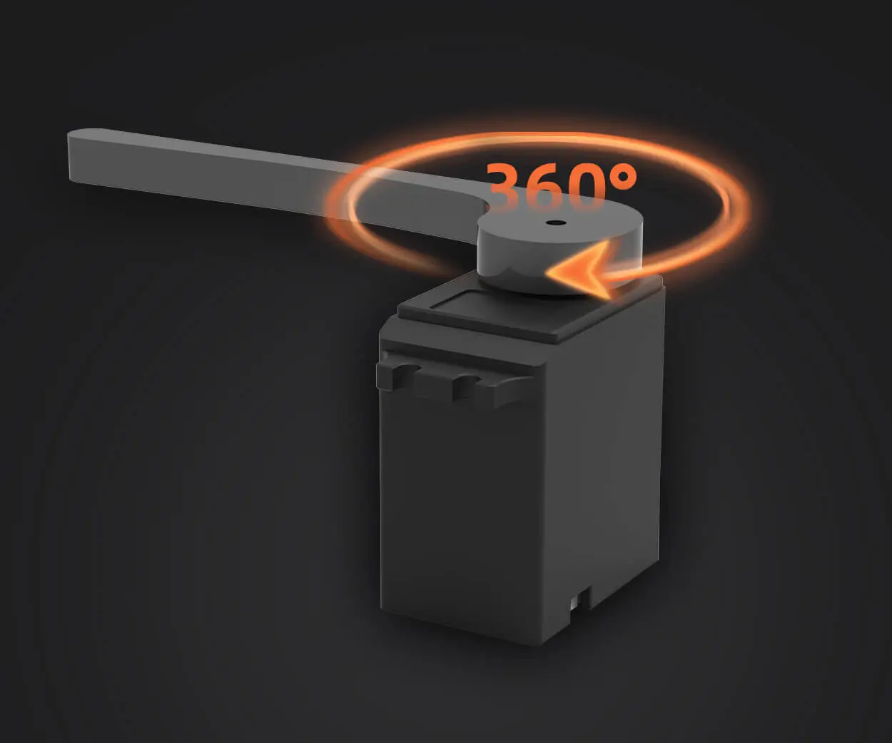
A servo motor is a compact electric device capable of precise angular movements. Unlike regular motors that spin freely, a servo has built-in feedback mechanisms and control circuitry that allow you to command specific positions or speeds. This makes it a perfect component for robotic arms, steering mechanisms, and any project where controlled movement is essential.
Servo motors are typically categorized based on their torque, speed, size, and the power supply they require. For DIY projects and hobbyists, standard servos like the SG90 or MG90S are popular because of their affordability and ease of use. They operate on a simple PWM (Pulse Width Modulation) signal that tells the servo what position to hold.
Raspberry Pi Meets Servo: The Winning Combo
The Raspberry Pi, a miniature computer that runs Linux, is a favorite among hobbyists and professionals alike for its versatility and affordability. Connecting a servo motor to the Pi transforms a simple circuit into an interactive robot that can respond to sensors, user commands, or even AI algorithms.
However, powering and controlling servos via the Pi must be done carefully. Servos often draw more current than the Pi can safely supply through its GPIO pins, raising risks of damage or unreliable operation. That's why designing an efficient circuit diagram is critical—not just to make the project work, but to ensure reliability and safety.
Basic Components Needed for the Circuit
Before we delve into the diagram, here’s a quick rundown of what you’ll need:
Raspberry Pi (any model with GPIO pins): This acts as the control hub. Servo Motor: An SG90 or comparable micro servo as a starting point. External Power Supply: Usually a 5V power adapter with sufficient current (at least 1A for multiple servos). Breadboard and Jumper Wires: For prototyping and connecting components easily. Resistors: Often a 220Ω resistor for signal line protection. Optional Components: A transistor (e.g., NPN like 2N2222) or a motor driver if you plan to control multiple or high-torque servos.
Understanding the Connection Points
Let’s visualize the basic connections:
Servo Signal Line (Control): Connects to a GPIO pin on the Pi. Servo Power (Vcc): Should be supplied from a dedicated 5V power source, not directly from the Pi’s 5V pin. Servo Ground (GND): Connects to both the Pi ground and the external power supply ground to ensure a common reference point.
This simple setup—though straightforward—must be executed carefully to prevent damage to your Pi and servo. Now, let’s focus on designing a robust circuit diagram that addresses these basics.
Designing the Circuit Diagram: Step-by-Step
The Raspberry Pi’s 5V GPIO pin can power small servos, but it’s better to use an external power source to supply the servo’s motor because they can draw significant current, especially under load. Using a separate power supply reduces stress on the Pi and maintains stable operation.
The external power supply should be regulated to 5V and capable of delivering at least 1A, depending on the number and size of servos.
Connecting Power and Ground Connect the positive terminal of the external power supply to the servo’s Vcc. Connect the negative (ground) terminal to both the servo’s GND and the Pi's GND pin on the GPIO header. This shared ground ensures the PWM signals are correctly interpreted. Connecting the Signal Line Use a resistor (220Ω) in series with the data line to limit current and protect the GPIO pin. Connect the resistor to a GPIO pin configured for PWM control, for example, GPIO18. Connect the other end of the resistor to the servo’s control wire (usually yellow or white). Finalizing the Circuit Double-check all connections, ensuring all grounds are common. Ensure that the power supply’s voltage and current ratings are appropriate. Add a capacitor (like 100μF) across the power supply lines near the servo to smooth out voltage fluctuations.
Visualizing the Circuit Diagram
Imagine looking at a simple schematic: On one side, the external 5V power supply, with its positive connected to the servo’s Vcc line and negative connected to both the servo ground and the Pi’s GND pin. From the Pi’s GPIO pin, a resistor connects to the servo’s control wire, providing the PWM signal. The entire setup is stabilized with a capacitor across the power lines.
Safety Tips and Best Practices
Always turn off your power supply before making connections to avoid shorts. Use a multimeter to verify voltage levels before powering up the system. Protect your Pi’s GPIO pins from voltage spikes—resistors and filtering capacitors are your friends. Label your wiring to avoid confusion during troubleshooting.
That covers Part 1, offering a solid foundation for understanding the circuit diagram essentials for a servo motor with Raspberry Pi. In Part 2, we’ll explore more advanced configurations, programming hints, troubleshooting tips, and real-world project ideas that bring this circuit to life. Ready to get those servos dancing? Stay tuned!
Leveraging innovations in modular drive technology, Kpower integrates high-performance motors, precision reducers, and multi-protocol control systems to provide efficient and customized smart drive system solutions.
Update:2025-10-15
Contact Kpower's product specialist to recommend suitable motor or gearbox for your product.


